1-43
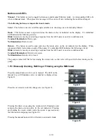
Figure A
Figure B
Figure C
If oil is surrounding the heater, the oil will
prevent the heater from ever reaching its
setpoint. Once oil is removed during
filtration the heater reaches setpoint and
cycles a thermostat every four seconds.
Since the cycle is only four seconds, the
seven second delay is not made and the
gas valve won’t open.
The 120VAC (220-240VAC on Intl.
units) is on T1 and T2 in the control box.
It is switched with 12 volts traveling in
from pin 5 of J3 and out to pins 5 and 7 on
AIF J2 and back in on pin 8 from AIF J2
(DV) or pin 6 from AIF J2 (FV) across the
relay coil.
Figure 26 Figure 27
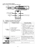
1.17.5.1 Oil Level Sensor Troubleshooting
Typical Sensor Related Failures
- Low temp but no call for heat (heat light)
-Intermittent IS VAT FULL? displays are primarily due to
dirty OIB sensors or loose grounds. Ensure that the OIB
sensors are clean as shown in Figure A.
This is usually due to a caramelized oil buildup on
the sensor. Clean the oil level sensor with a
scratch pad and power cycle the controller.
Check grounds from the OIB relay and 7 second
timer board delay. When grounded to the stud on
the interface board they have a tendency to loosen.
They should NOT be grounded to interface board
studs as shown in Figure B. If so they should be
moved and be tightly grounded to stud in rear of
the fryer as shown in Figure C.
- Stuck in melt cycle with no call for heat
- Filter error (IS VAT FULL?) with oil in the filter pan (no
oil in the vat)
If the controller doesn’t exit melt cycle or continues to
display low temp and does not heat, and gas supply, gas
valve, etc. have been checked and no heat lamp illuminates because no call for heat is initiated, then follow
these steps:
- Check (see diagram next page)
- Power to oil sensor (from oil level sensor relay in component box). Check pin 5 on AIF J2 (DV) or
pin 7 on AIF J2 (FV) for 12VDC from interface board.
- Power to heater/relay coil on relay board. Check voltage to the coil between pins 8 and 1 to ensure
that 120VAC (220-240VAC on Intl. units) is present with oil in the vat. If the vat is empty, the
power will cycle 4 seconds on, 4 seconds off.
- Check between pin 3 and 2 on the relay board reads 5VDC for air and 0VDC for oil. A common
message for a shorted harness or issue is “IS DRAIN CLEAR?” with oil in the filter pan.
- Check ground on pin 2 on relay board to stud for a secure ground.
- Check AIF communication harness. Interrupted communication will prevent the fryer from heating.
- If the oil level sensor is cycling 4 sec. on/off and oil is surrounding the sensor, the sensor may have
a carbon build up that is self insulating the sensor. Use a scratch pad to remove carbon build up.
Содержание Frymaster FilterQuick 2FQG30U
Страница 8: ...1 3 ...
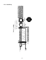
Страница 41: ...1 36 1 16 2 Bulk Wiring ...
Страница 56: ...1 51 1 18 6 Clogged Drain Failed Oil Sensor Error Flowchart ...
Страница 57: ...1 52 1 18 7 Menu Trees 1 18 7 1 FilterQuick Controller Setup Menu Tree ...
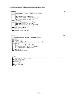
Страница 58: ...1 53 1 18 7 2 FilterQuick Filter and Info Mode Menu Tree ...
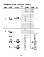
Страница 62: ...1 57 1 20 Principal Wiring Connections ...
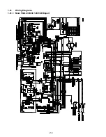
Страница 63: ...1 58 1 21 Wiring Diagrams 1 21 1 Main FQG 230 430 120V CE Export ...
Страница 64: ...1 59 1 21 2 Main FQG 230 430 Australia ...
Страница 65: ...1 60 1 21 3 Main FQG 230 430 120V CE Export with Solid Shortening ...
Страница 66: ...1 61 1 21 4 Main FQG 230 430 Australia with Solid Shortening ...
Страница 67: ...1 62 1 21 5 Main FQG 330 530 120V CE Export ...
Страница 68: ...1 63 1 21 6 Main FQG 330 530 Australia ...
Страница 69: ...1 64 1 21 7 Main FQG 330 530 120V CE Export with Solid Shortening ...
Страница 70: ...1 65 1 21 8 Main FQG 330 530 Australia with Solid Shortening ...
Страница 71: ...1 66 1 21 9 Transformer Filter Box 430 530 ...
Страница 72: ...1 67 1 22 Simplified Wiring Diagrams 1 22 1 FilterQuick FQG30 Series Simplified Wiring with Push Pull Handles ...
Страница 73: ...1 68 1 22 2 FilterQuick FQG30 Series Simplified Wiring with Push Buttons ...
Страница 74: ...1 69 1 22 3 FilterQuick FQG30 Series Data Network Flowchart ...
Страница 76: ...1 71 1 24 Shortening Melting Unit Wiring Diagram ...
Страница 77: ...1 72 1 25 Modular Basket Lift Wiring Diagram 100 120V 1 2 4 3 5 6 12 7 8050518E ...
Страница 79: ...1 74 1 27 Basket Lift Interface Harness ...


