1-6
6.
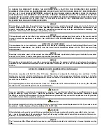
To adjust the burner gas pressure, remove the cap from the gas valve regulator and adjust to the correct
pressure.
Non-CE
Valve
CE
Valve
GAS VALVE REGULATOR CAP
7.
Place the fryer power switch (and the gas valve in non-CE fryers) in the OFF position. Remove the fitting
from the pressure tap hole and reinstall the pressure tap plug.
1.8
Measuring Flame Current
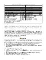
When the burner flame is properly adjusted, it will typically produce a current between 0.3
A and 0.9
A on
Capable Control modules or between 3.0
A and 8.0
A on Honeywell modules. Lockouts can occur at currents
0.15
A or below on Capable Control modules or 0.9
A or below on Honeywell modules. Flame current is
measured by placing a
microamp
(not milliamp) meter in series with the sensing wire on the ignitor. This is
accomplished as follows:
1.
Place the fryer power switch in the OFF position.
2.
Disconnect the sensing wire from one of the burner ignitors and connect it to the positive lead of the meter.
Connect the negative lead of the meter to the terminal from which the sensing wire was removed.
3.
Place the fryer power switch in the ON position to light the burners. After the frypot temperature reaches
200
F (93
C), wait at least one minute before checking the reading.
NOTE:
The closer the unit is to
normal operating temperature, the more accurate the reading will be.
1.9
Replacing Fryer Components
1.9.1 Replacing the Controller or the Controller Wiring Harnesses
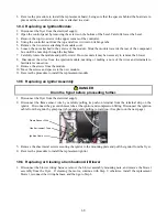
1.
Disconnect the fryer from the electrical power supply.
2.
Unscrew the filter push pull handle knobs.
3.
Open the control panel by removing the screws on the bottom of the bezel. Carefully lower the bezel.
4.
Remove the two screws from the upper corners of the controller. The controller is hinged at the bottom and
will swing open from the top.
5.
Unplug the wiring harnesses from the connectors on the back of the controller marking their position for
reassembly and disconnect the grounding wires from the terminals. Remove the controller by lifting it from
the hinged slots in the control panel frame.
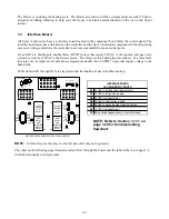
Flame Sensor Wire
Содержание Frymaster FilterQuick 2FQG30U
Страница 8: ...1 3 ...
Страница 41: ...1 36 1 16 2 Bulk Wiring ...
Страница 56: ...1 51 1 18 6 Clogged Drain Failed Oil Sensor Error Flowchart ...
Страница 57: ...1 52 1 18 7 Menu Trees 1 18 7 1 FilterQuick Controller Setup Menu Tree ...
Страница 58: ...1 53 1 18 7 2 FilterQuick Filter and Info Mode Menu Tree ...
Страница 62: ...1 57 1 20 Principal Wiring Connections ...
Страница 63: ...1 58 1 21 Wiring Diagrams 1 21 1 Main FQG 230 430 120V CE Export ...
Страница 64: ...1 59 1 21 2 Main FQG 230 430 Australia ...
Страница 65: ...1 60 1 21 3 Main FQG 230 430 120V CE Export with Solid Shortening ...
Страница 66: ...1 61 1 21 4 Main FQG 230 430 Australia with Solid Shortening ...
Страница 67: ...1 62 1 21 5 Main FQG 330 530 120V CE Export ...
Страница 68: ...1 63 1 21 6 Main FQG 330 530 Australia ...
Страница 69: ...1 64 1 21 7 Main FQG 330 530 120V CE Export with Solid Shortening ...
Страница 70: ...1 65 1 21 8 Main FQG 330 530 Australia with Solid Shortening ...
Страница 71: ...1 66 1 21 9 Transformer Filter Box 430 530 ...
Страница 72: ...1 67 1 22 Simplified Wiring Diagrams 1 22 1 FilterQuick FQG30 Series Simplified Wiring with Push Pull Handles ...
Страница 73: ...1 68 1 22 2 FilterQuick FQG30 Series Simplified Wiring with Push Buttons ...
Страница 74: ...1 69 1 22 3 FilterQuick FQG30 Series Data Network Flowchart ...
Страница 76: ...1 71 1 24 Shortening Melting Unit Wiring Diagram ...
Страница 77: ...1 72 1 25 Modular Basket Lift Wiring Diagram 100 120V 1 2 4 3 5 6 12 7 8050518E ...
Страница 79: ...1 74 1 27 Basket Lift Interface Harness ...


