background image


1-54

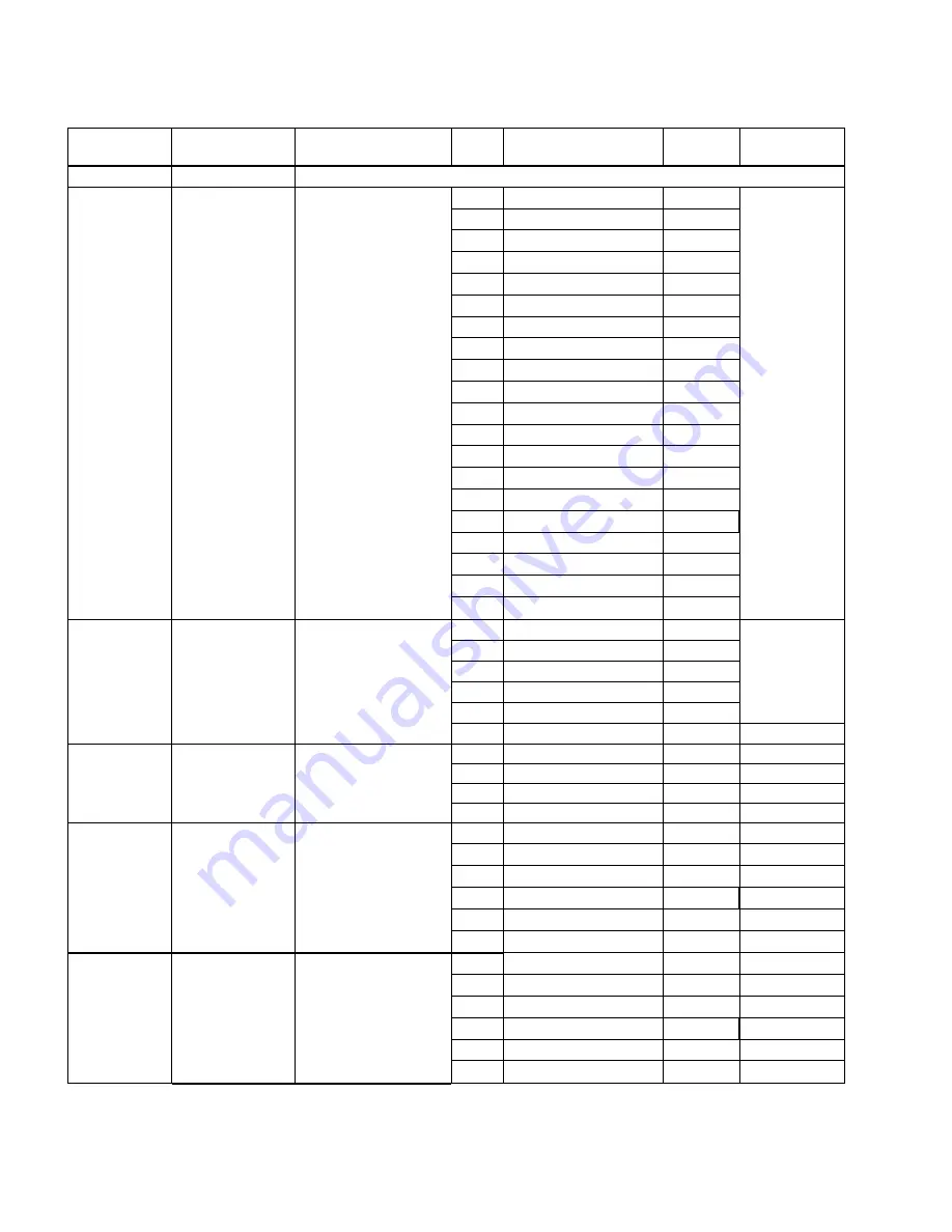
1.18.8   FilterQuick

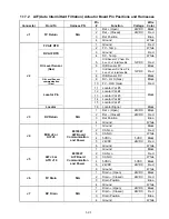
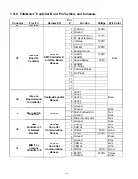
 Controller Board Pin Positions and Harnesses 


Connector From/To 

Harness 

PN 

Pin 

# Function 

Voltage 

Wire 

Color 

J1 SD 

Card 


J2 

Interface 

Board to 

Controller 

8075165            

SMT Controller to 

Interface Board 

Harness 

1 12VAC 

In 

12VAC 

Black 

2 Ground 


3  12VAC Return In 

12VAC 

4  FV Heat Demand 


5 V 

Relay 

12VDC 

6  DV Heat Demand 


7 R/H 

B/L 

12VDC 

8  Analog Ground 


9 L/H 

B/L 

12VDC 

10 ALARM 


11 Sound 

Device 

5VDC 

12 ALARM 


13  FV Probe 


14  Common Probes 


15  DV Probe 


16  


17   


18   


19   


20   


J3 

Interface 

Board Ground 

to Controller 

Controller Locator 

Harness 

1 Vat 

#1 


Black 

2 Vat 

#2 


3 Vat 

#3 


4 Vat 

#4 


5 Vat 

#5 


6 Ground 


J4 

Drain Switch 

and LED 

1085672 

1 Ground 


Black 

2  Push Pull Switch In 


Red 

3 Ground 


Black 

4  Drain Indicator LED 


Red 

J6 

Next 

Controller J7 

or Network 

Resistor 

8074546            

Controller 

Communication 

Harness 

1 Ground 


Black 

2  CAN Lo 


Red 

3  CAN Hi 


White 

4 5VDC+ 

5VDC  Green 

5 24VDC 

24VDC  Yellow 

6  Ground  

Brown 

J7 

MIB J1 or       

previous 

Controller J6 

8074546            

Controller 

Communication 

Harness 

1 Ground 


Black 

2  CAN Lo 


Red 

3  CAN Hi 


White 

4 5VDC+ 

5VDC  Green 

5 24VDC 

24VDC  Yellow 

6  Ground  

Brown 


Содержание Frymaster FilterQuick 2FQG30U

Страница 1: ...w information and models are released Visit our website for the latest manual Part Number FRY_SM_8197109 09 2017 8197109 FOR YOUR SAFETY Do Not Store or use gasoline or other flammable vapors and liquids in the vicinity of this or any other appliance Original Instructions ...

Страница 2: ... operational procedures NOTICE This appliance is intended to be used for commercial applications for example in kitchens of restaurants canteens hospitals and in commercial enterprises such as bakeries butcheries etc but not for continuous mass production of food NOTICE TO OWNERS OF UNITS EQUIPPED WITH CONTROLLERS U S This device complies with Part 15 of the FCC rules Operation is subject to the f...

Страница 3: ...servicing of this product could expose you to airborne particles of glasswool or ceramic fibers crystalline silica and or carbon monoxide Inhalation of airborne particles of glasswool or ceramic fibers is known to the State of California to cause cancer Inhalation of carbon monoxide is known to the State of California to cause birth defects or other reproductive harm DANGER The crumb tray in fryer...

Страница 4: ... 19 1 10 5 Filtration Malfunctions 1 19 1 10 6 Leakage 1 20 1 11 Troubleshooting Guides 1 20 1 11 1 Troubleshooting the 24 VAC Circuit 1 20 1 11 2 Troubleshooting the Gas Valve 1 22 1 11 3 Troubleshooting the Temperature Probe 1 23 1 11 4 Replacing the Transformer or Filter Relay 1 23 1 12 Basket Lift Service Procedures 1 24 1 13 Probe Resistance Chart 1 26 1 14 ATO Automatic Top Off Service Proce...

Страница 5: ...dures 1 56 1 20 Principal Wiring Connections 1 57 1 21 Wiring Diagrams 1 58 1 21 1 Main FQG 230 430 120V CE Export 1 58 1 21 2 Main FQG 230 430 Australia 1 59 1 21 3 Main FQG 230 430 120V CE Export with Solid Shortening 1 60 1 21 4 Main FQG 230 430 Australia with Solid Shortening 1 61 1 21 5 Main FQG 330 530 120V CE Export 1 62 1 21 6 Main FQG 330 530 Australia 1 63 1 21 7 Main FQG 330 530 120V CE...

Страница 6: ... full and dual vat fryers use two single spark modules The ignitor assembly consists of a spark plug an enrichment tube and a flame sensor At start up the power switch is placed in the ON position supplying approximately 12 volts DC to the heat control circuitry in the controller and to one side of the heat relay coils on the interface board If resistance in the temperature probe indicates the tem...

Страница 7: ...gh D7 are arrayed around the board to assist in troubleshooting K4 K1 SOUND GND V2D PWR AD AS V2S GND GV PWR 12V AIR 24V PWR GND V1D PWR ALR V1S GV GND J2 SMT INTERFACE BOARD KIT 826 2264 106 6706 J3 3 6 9 12 2 5 8 11 1 4 7 10 J1 3 6 9 12 2 5 8 11 1 4 7 10 15 12 9 6 3 14 11 8 5 2 13 10 7 4 1 K2 K3 HEAT RELAY AND BLOWER MOTOR RELAY D1 D2 D3 D4 D6 D7 D5 HEAT RELAY AND BLOWER MOTOR RELAY F2 Ignition ...

Страница 8: ...1 3 ...

Страница 9: ... monitors the probe resistance and controls burner firing when the resistance exceeds or falls below programmed temperatures setpoints FilterQuick FQG30 Series gas fryers are also equipped with a high limit thermostat In the event that the fryer fails to properly control the oil temperature the high limit thermostat prevents the fryer from overheating to the flash point The high limit thermostat a...

Страница 10: ...teadily for at least one minute compare the gas pressure reading to the pressure for the corresponding gas in the appropriate table on the following page The tables list the burner manifold gas pressures for each of the gas types that can be used with this equipment Gas Single Vat Dual Vat Natural Gas Lacq G20 under 20 mbar 7 8 Natural Gas Gronique G25 under 25 mbar 10 11 2 Natural Gas Gronique G2...

Страница 11: ...onnect it to the positive lead of the meter Connect the negative lead of the meter to the terminal from which the sensing wire was removed 3 Place the fryer power switch in the ON position to light the burners After the frypot temperature reaches 200 F 93 C wait at least one minute before checking the reading NOTE The closer the unit is to normal operating temperature the more accurate the reading...

Страница 12: ...12 Remove the component box mounting screws 13 Rotate the top of the component box out of the frame and carefully pull it out enough to disconnect the wiring harness plug from the back of the box This will leave one set of wires enclosed in spiral wrap connected to the component box 14 Remove the box and set it atop the fryer to expose the temperature probe and high limit thermostat 15 Unscrew the...

Страница 13: ...ion 9 Remove the screws from the module 10 Move the screws and spacers to the new module 11 Reverse the procedure to install the replacement module 1 9 5 Replacing an Ignitor Assembly DANGER Drain the frypot before proceeding further 1 Disconnect the fryer from the electrical supply 2 Disconnect the flame sensor wire by carefully pulling its push on terminal from the terminal strip on the ignitor ...

Страница 14: ...d the blower housing Allow it to soak for five minutes Rinse the wheel and housing with hot tap water then dry with a clean cloth NOTICE Australia Only The air pressure switch on the combustion blower should read Full Vat units 122pa 0 5 inches W C and for Split Vat units 180pa 0 72 inches W C Blower Housing Blower Wheel Wrap the motor and wires with plastic wrap or a plastic bag 4 Remove the plas...

Страница 15: ...the shutter to be moved then adjust the position of the shutter to open or close the air intake opening until a bright orange red glow is obtained then close it slightly Carefully hold the shutter in position and tighten the locking nut see illustration on the following page 1 9 8 Replacing a Gas Valve 1 Disconnect fryer from electrical and gas supplies 2 Disconnect the drain safety and high limit...

Страница 16: ...equivalent pipe thread sealant 6 Reconnect the gas valve assembly to the fryer using Loctite PST56765 or equivalent pipe thread sealant and reattach the flexible gas line s enrichment tube s and the vent tube on non CE units Reconnect the high limit thermostat wires and drain safety wires to the valve 7 Reconnect the fryer to the gas supply and open the cut off valve Apply a thick soapy solution o...

Страница 17: ...rn fitting at the front of the cabinet Disconnect the flexible oil line from the fitting allowing any residual oil to drain into the container 4 At the rear of the fryer unplug the left connector as viewed from the rear of the fryer from the transformer box 5 Remove the four nuts and bolts attaching the motor mount to the rear motor mount support 6 At the front of the fryer remove the cover plate ...

Страница 18: ...the temperature probe high limit thermostat wires and RTD probe wires from the plugs or terminals marking each wire to facilitate re assembly 12 Disconnect the actuators from the return and drain valves 13 Remove the section s of drain from the drain valve s of the frypot to be removed 14 Disconnect the gas lines from the burner orifices and ignitor assemblies 15 Remove the frypot hold down bracke...

Страница 19: ...9 Remove the rear lower combustion chamber retainers back and insulation 9 NOTE Full vat units have two piece backs and four retainers Dual vat units have one piece backs and two retainers 10 Remove the flue assembly 10 Disassembling A Frypot Full Vat Illustrated Spacers Spacer 10 2 3 4 5 6 7 8 1 11 9 See page 1 16 for reassembly illustration 11 Remove the upper burner rails 11 NOTE For the follow...

Страница 20: ...he excess burner insulation by cutting with a knife or diagonal pliers Do not try to tear the insulation 25 Insert the upper front insulation 10 into its retainer 11 making sure that the holes in each piece are aligned with one another Install the assembly with the insulation side toward the frypot and secure with 20 washer nuts Do not over tighten 26 Place a washer on each of the four lower studs...

Страница 21: ...can be grouped into six categories 1 Ignition failure 2 Improper burner function 3 Improper temperature control 4 Controller malfunctions 5 Filtration malfunctions 6 Leakage The probable causes of each category are discussed in the following sections A series of Troubleshooting Guides is also included at the end of the chapter to assist in solving some of the more common problems 1 10 1 Heating Ig...

Страница 22: ...unit is again closed up and placed back into service the module heats up and fails PROBLEMS RELATED TO THE GAS VALVE If the problem is not in the 24 VAC circuit it is most likely in the gas valve itself Before replacing the gas valve refer to Section 1 11 2 TROUBLESHOOTING THE GAS VALVE 1 10 2 Improper Burner Function With problems in this category the burner ignites but exhibits abnormal characte...

Страница 23: ...here are usually caused by air conditioning and or ventilation units starting and stopping during the day As they start and stop the pressure in the kitchen may change from positive or neutral to negative or vice versa They may also cause changes in airflow patterns that may affect flame intensity Dark spots on the burner tiles are the result of an improper air gas mixture Adjust the combustion ai...

Страница 24: ...ngs will allow the pump to suck air and decrease its efficiency If the pump motor overheats its thermal overload will trip and the motor will not start until it is reset If the pump motor does not start press the red reset switch located on the front of the motor If the pump then starts something caused the motor to overheat It may be just that several frypots in a large battery of fryers were bei...

Страница 25: ...ator troubleshooting guides are contained in Chapter 6 of the FilterQuick FQG30 Series Installation and Operation Manual It is suggested that service technicians thoroughly familiarize themselves with both sets 1 11 1 Troubleshooting the 24 VAC Circuit Prior to checking for problems associated with the 24 VAC circuit ensure that the unit is connected to a power supply the drain valve is fully clos...

Страница 26: ...mit thermostat If it is zero problem is in wiring 2 If 24 VAC is present across the gas valve main coil MV terminals the 24 VAC circuit is working and the problem may be with the gas valve Be sure to check both valves on dual vat units ...

Страница 27: ...g for heat Also for non CE units verify that the gas valve is in the ON position The following processes will assist you in troubleshooting the gas valve and ruling it out as a probable cause If 24 VAC is not present across gas valve main coil the probable cause is the 24 VAC circuit Refer to the 24 VAC circuit troubleshooting guide ...

Страница 28: ...ace the probe The following processes will assist you in troubleshooting the gas valve and ruling it out as a probable cause Before testing the probe determine the temperature the cooking oil using another thermometer or pyrometer placed at the tip of the questionable probe If resistance through J3 pins 2 and 6 J1 pins 2 and 6 for left side of dual unit is not approximately equal to that given in ...

Страница 29: ...stop the motor at the lift s upper and lower travel limits and reverse the direction of current flow thus reversing the motor direction When the product button is pushed on the controller current flows through a coil in the basket lift relay causing the lower circuit to be activated The basket lift lowers closing the normally open upper micro switch When the downward moving rod opens the lower nor...

Страница 30: ...o the frypot the problem is a failed motor brake A failed motor brake cannot be repaired and requires replacement of the motor itself If power is reaching the motor but the motor fails to run the motor is burned out and must be replaced Electronic Issues Within this category are problems associated with the relays microswitches capacitors resistors interface board wiring and controls The most comm...

Страница 31: ...s The automatic top off system is activated when the oil level falls below a sensor in the front of the frypot The signal is sent to the ATO board to engage the return actuator to the frypot and turn on the ATO pump The pump draws oil from the JIB Jug In Box through the rear return manifold into the rear of the frypot Once the oil level has satisfied the sensor the pump turns off and the actuator ...

Страница 32: ...tional Check voltage to pump Replace the pump if defective I Check for proper voltages using the pin position chart found on page 1 28 If ATO found defective replace ATO board J Clear the lines pump Incorrect vat tops off A Wired incorrectly B Flexlines connected to wrong vat A Check wiring B Switch flexlines to correct vat One vat doesn t top off A Filter error exists B Actuator pump loose connec...

Страница 33: ...er 8074553 1 24VAC Ret 24VAC Orange 2 24VAC Blue 3 4 5 12VAC Ret 12VAC Red 6 12VAC Brown ATO 4 5 Battery Jumper 8074657 7 Jumper Ohm Black 8 Jumper Black J1 Vat 1 J2 Vat 2 J3 Vat 3 ATO RTD 8262569 Probe Kit 8074845 28 Ext 8074655 20 Ext 1 DV Probe Ground Ohm White 2 DV Probe Red 3 FV Probe Ground White 4 FV Probe Red J6 J10 Network Resistor pins 2 3 or to next ATO Board 4 5 vat units 8074552 Netwo...

Страница 34: ...ATO box Mark and unplug any wires or harnesses Press up from the bottom on the quick disconnects to release the plumbing see Figure 5 The plumbing can be pulled from the pump Loosen the four nuts attaching the pump to the pump tray Replace the defective component and reverse above steps Once replaced reconnect the power Figure 4 Figure 5 1 15 MIB Manual Interface Board Service Procedures The MIB M...

Страница 35: ...n pressed and held it also turns on and off the pump It s embedded LED indicates the following activity Blink Actuator is moving or awaiting a response from the AIF board or an error condition exists Constant Illumination Return valve open No Illumination Return valve closed The pump is turned off first before closing the return valve or the valve will open first before turning on the pump 1 15 1 ...

Страница 36: ...ould read 24VAC If not replace transformer MIB will not clear error Error remains in non volatile memory Press and hold reset button in top right corner of MIB board for five seconds The drain return and manual auto LEDS will illuminate and the MIB will reset and clear any remaining errors from memory Allow 60 seconds to reset If an error still exists then another issue exists MIB indicates incorr...

Страница 37: ...n the 110V to the ATO transformer may be missing or bad The J4 J5 connector may be loose D Check to see if MIB has 24V on pins 5 and 6 of J2 Check to see if 24V is present on pins 5 and 6 of wire harness plugging into J4 or J5 of the first AIF board If 24V missing check the pins Replace the harness if necessary E Check continuity between each color wire on the CAN connectors into J7 on the far rig...

Страница 38: ...ulk 1 24VAC In 24VAC Black 2 24VAC In Ret White Filter Relay 3 Pump Motor Out 24VDC Red 4 Pump Motor Out Green 5 6 Bulk Open Switch 7 Open Switch Black Bulk Closed Switch 8 Closed Switch Red 9 10 Pan Switch 11 Pan Sw 24VDC Black 12 Pan Sw Red 13 14 Bulk Open Switch 15 Ground White Bulk Closed Switch 16 Ground Green J6 To Bulk connection in rear of fryer 8075789 1 From bulk oil transformer 24VAC Bl...

Страница 39: ... which correspond to the vats with either an L indicating the left side of a split vat or r indicating the right side of a split vat or a full vat These numbers are displayed in manual mode 1 15 5 Replacing the MIB Board Disconnect the fryer from the electrical power supply Remove the torx screw from the bottom of the MIB cover exposing the MIB board see Figure 11 Remove the two cabinet screws at ...

Страница 40: ...ng the Bulk test box PN 108 0716 allows a quick and easy way to check the 24VAC the waste full switch and when the bulk fresh oil pump is operating Troubleshooting All return and drain valves should be closed and pump should be off while the MIB is resetting If any of the valves or the pump is on during reset the MIB board is bad or wires are shorted Bulk fresh oil pump is not operating or JIB is ...

Страница 41: ...1 36 1 16 2 Bulk Wiring ...

Страница 42: ...ress Yes to dispose of oil in pot 5 Start Dispose is displayed with blinking LED 6 Pull the drain handle 7 Draining followed by Flushing is displayed 8 Vat Empty Confirm is displayed 9 Press Confirm 10 Close Drain is displayed with blinking LED 11 Push the drain handle in towards the fryer 12 Open Dispose Valve is displayed 13 Open dispose valve by pulling completely forward to start disposal 14 D...

Страница 43: ...an slightly out of the fryer 17 Is Pan Empty Yes No is displayed 18 Press Yes if filter pan is empty Select No if pan still has oil in it 19 Insert Filter Pan is displayed 20 Insert the filter pan 21 Close Dispose Valve is displayed 22 Close dispose valve ensuring the handle is pushed completely towards the fryer 23 Fill Vat From Bulk Yes No is displayed 24 Press No if you wish to leave pot empty ...

Страница 44: ...if they have a bulk fresh oil unit with a single head Some bulk fresh oil units have dual heads which can fill more than one fryer simultaneously 1 17 AIF Automatic Intermittent Filtration Service Procedures The AIF Automatic Intermittent Filtration board controls the actuators that open and close the drain and return valve The AIF boards are located inside a protective housing under each frypot s...

Страница 45: ...ugging into another connector If the actuator operates replace the board D Check resistance of the potentiometer between pin 3 blue wire and pin 4 gray white wire Closed should read 0 560Ω Open should read 3 8K Ω 6 6K Ω E If proper voltages are present at the connector and actuator doesn t operate reset power to the fryer if it still doesn t operate replace the actuator Actuator functions on wrong...

Страница 46: ...10 FV OLS Gas Red Locator Pin 11 Locator Vat 5 Black 12 Locator Vat 4 13 Locator Vat 3 14 Locator Vat 2 15 Locator Vat 1 Locator 16 Locator Signal Black J3 DV Return N A 1 Ret Open 24VDC Black 2 Ret Closed 24VDC Red 3 Ret Position Blue 4 Ground White J4 MIB J2 or AIF J5 8074547 AIF Board Communication and Power 1 Ground Black 2 CAN Lo Red 3 CAN Hi White 4 5VDC 5VDC Black 5 24VDC 24VDC Red 6 Ground...

Страница 47: ...actuators are held in place by two hex key screws Loosen the 3 32 hex key screws It may be necessary to remove a gas line to the burner when removing a drain actuator Remove the actuator from the valve stem Align the actuator with the valve stem and attach the new actuator Tighten the two hex key screws Reconnect power and test the actuator NOTE Rotary actuators have two different part numbers and...

Страница 48: ...ds as shown in Figure B If so they should be moved and be tightly grounded to stud in rear of the fryer as shown in Figure C Stuck in melt cycle with no call for heat Filter error IS VAT FULL with oil in the filter pan no oil in the vat If the controller doesn t exit melt cycle or continues to display low temp and does not heat and gas supply gas valve etc have been checked and no heat lamp illumi...

Страница 49: ...switch to turn the controller on B If the controller cord is not plugged in the controller will not activate Verify controller power cord is plugged in and that circuit breaker is not tripped C Swap the controller with a controller known to be good If controller functions replace the controller D Swap with a harness known to be good If controller functions replace the harness E If any component in...

Страница 50: ...llow prompts Pressing NO will allow the fryer to cook in most cases but error will be redisplayed every 15 minutes Controller display is in wrong temperature scale Fahrenheit or Celsius Incorrect display option programmed See section 1 18 2 on page 1 47 to change temperature scale Controller displays CHANGE FILTER PAPER Filter error has occurred filter paper clogged 24 hour filter pad change promp...

Страница 51: ... Controller in high limit test mode This is displayed during a test of the high limit circuit to indicate if the high limit has failed Controller displays HELP HI 2 or HIGH LIMIT FAILURE Failed high limit This is displayed to indicate the high limit has failed Fryer filters after each cook cycle Filter after setting incorrect or software update issue Overwrite the filter after setting by re enteri...

Страница 52: ...rify CAN communication Check AIF connections from AIF board J2 pin 9 DV or pin 10 FV to pin 3 of time delay relay board Check OIB relay time delay relay board in component box Controller displays IS OIL SENSOR CLEAM CONFIRM during a cook or in idle mode with an audible alarm A The oil level sensor may be coated with caramelized oil B OIB relay ground issue C CAN communication issues component fail...

Страница 53: ...SYSTEM ERROR FIXED YES NO Press YES if fixed If NO is chosen the system returns to cook mode for 15 minutes then redisplays error until issue is fixed 1 18 4 Error Log Codes Refer to page 1 52 Vat Setup for access to the E log The ten most recent errors are listed from A J with A being the most recent error CODE ERROR MESSAGE EXPLANATION E03 ERROR TEMP PROBE FAILURE Temp probe reading out of range...

Страница 54: ...19 4 C below setpoint E28 HIGH TEMP ALARM Oil temperature has risen 40 F 22 2 C higher than setpoint If temperature continues to rise the high limit will shut the burner off when temperature reaches 425 F 218 C Non CE or 395 F 202 C CE E70 OQS TEMP HIGH Oil temperature is too high for a valid OQS reading Filter at a temperature between 300ºF 149ºC and 375ºF 191ºC E71 OQS TEMP LOW Oil temperature i...

Страница 55: ...is chart follows the process of clearing a filtration issue The prompt is displayed when any of the following occur 1 a clogged filter paper 2 a tripped or defective filter pump 3 a leaky O ring on the pick up tube 4 a failed drain valve actuator or 5 a failed return valve actuator If the controller displays SERVICE REQUIRED the fryer can be used in most cases by answering NO when the prompt for S...

Страница 56: ...1 51 1 18 6 Clogged Drain Failed Oil Sensor Error Flowchart ...

Страница 57: ...1 52 1 18 7 Menu Trees 1 18 7 1 FilterQuick Controller Setup Menu Tree ...

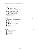
Страница 58: ...1 53 1 18 7 2 FilterQuick Filter and Info Mode Menu Tree ...

Страница 59: ...4 Common Probes 15 DV Probe 16 17 18 19 20 J3 Interface Board Ground to Controller Controller Locator Harness 1 Vat 1 Black 2 Vat 2 3 Vat 3 4 Vat 4 5 Vat 5 6 Ground J4 Drain Switch and LED 1085672 1 Ground Black 2 Push Pull Switch In Red 3 Ground Black 4 Drain Indicator LED Red J6 Next Controller J7 or Network Resistor 8074546 Controller Communication Harness 1 Ground Black 2 CAN Lo Red 3 CAN Hi W...

Страница 60: ...are both present and that they are not missing cracked or worn If so replace them D Ensure the filter paper is not clogged and clean filter paper is used Did the vat refill the first time for the previous filter If not change the filter paper E Dispose of the oil F Check error log for any OQS errors E70 76 See explanation and solution in section 1 18 4 Controller does not display OQS software vers...

Страница 61: ...ft and the percentage complete on the right 7 The display then changes to REMOVE SD CARD on the left and 100 on the right 8 Remove the SD card using the fingernail slot on the top of the SD card 9 Once the SD card is removed the display changes to CYCLE POWER 10 Cycle the control power using the hidden reset switch behind the right control box ENSURE THE SWITCH IS HELD FOR 10 SECONDS WAIT ANOTHER ...

Страница 62: ...1 57 1 20 Principal Wiring Connections ...

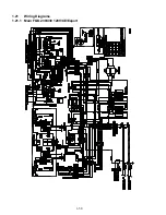
Страница 63: ...1 58 1 21 Wiring Diagrams 1 21 1 Main FQG 230 430 120V CE Export ...

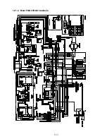
Страница 64: ...1 59 1 21 2 Main FQG 230 430 Australia ...

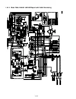
Страница 65: ...1 60 1 21 3 Main FQG 230 430 120V CE Export with Solid Shortening ...

Страница 66: ...1 61 1 21 4 Main FQG 230 430 Australia with Solid Shortening ...

Страница 67: ...1 62 1 21 5 Main FQG 330 530 120V CE Export ...

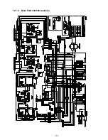
Страница 68: ...1 63 1 21 6 Main FQG 330 530 Australia ...

Страница 69: ...1 64 1 21 7 Main FQG 330 530 120V CE Export with Solid Shortening ...

Страница 70: ...1 65 1 21 8 Main FQG 330 530 Australia with Solid Shortening ...

Страница 71: ...1 66 1 21 9 Transformer Filter Box 430 530 ...

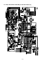
Страница 72: ...1 67 1 22 Simplified Wiring Diagrams 1 22 1 FilterQuick FQG30 Series Simplified Wiring with Push Pull Handles ...

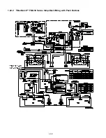
Страница 73: ...1 68 1 22 2 FilterQuick FQG30 Series Simplified Wiring with Push Buttons ...

Страница 74: ...1 69 1 22 3 FilterQuick FQG30 Series Data Network Flowchart ...

Страница 75: ...1 70 1 23 Alternate 7 sec Time Delay Relay Wiring Diagrams PN 807 4934 220V 250V Intl Units PN 807 4812 120V US Canada Mexico ...

Страница 76: ...1 71 1 24 Shortening Melting Unit Wiring Diagram ...

Страница 77: ...1 72 1 25 Modular Basket Lift Wiring Diagram 100 120V 1 2 4 3 5 6 12 7 8050518E ...

Страница 78: ... 12 5 NO NC NC NO 1 2 3 4 NO NC 5 6 REFERENCES TO LEFT RIGHT ARE FROM THE REAR OF THE FRYER 8050946B LOWER SWITCH LOWER SWITCH UPPER SWITCH UPPER SWITCH NOT USED ON 208 220V BRN 1 RED 1 BRN 2 RED 2 101C 93C BLK BLK 25ohm 25ohm 98C 96C 95C 97C 100C 32C 4C 29C 61C 10C 3C 100ohm 100ohm 8C 15C COM COM COM COM LEFT SIDE RIGHT SIDE ...

Страница 79: ...1 74 1 27 Basket Lift Interface Harness ...

Страница 80: ...Y_SM_8197109 09 2017 8197423 WWW WELBILT COM Welbilt provides the world s top chefs and premier chain operators or growing independents with industry leading equipment and solutions Our cutting edge designs and lean manufacturing tactics are powered by deep knowledge operator insights and culinary expertise All of our products are backed by KitchenCare our aftermarket repair and parts service CLEV...

Отзывы: