1-42
1.17.3 Replacing an AIF (Automatic Intermittent Filtration) Board
Disconnect the fryer from the electrical power supply. Locate the AIF board to be replaced under a frypot.
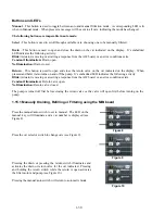
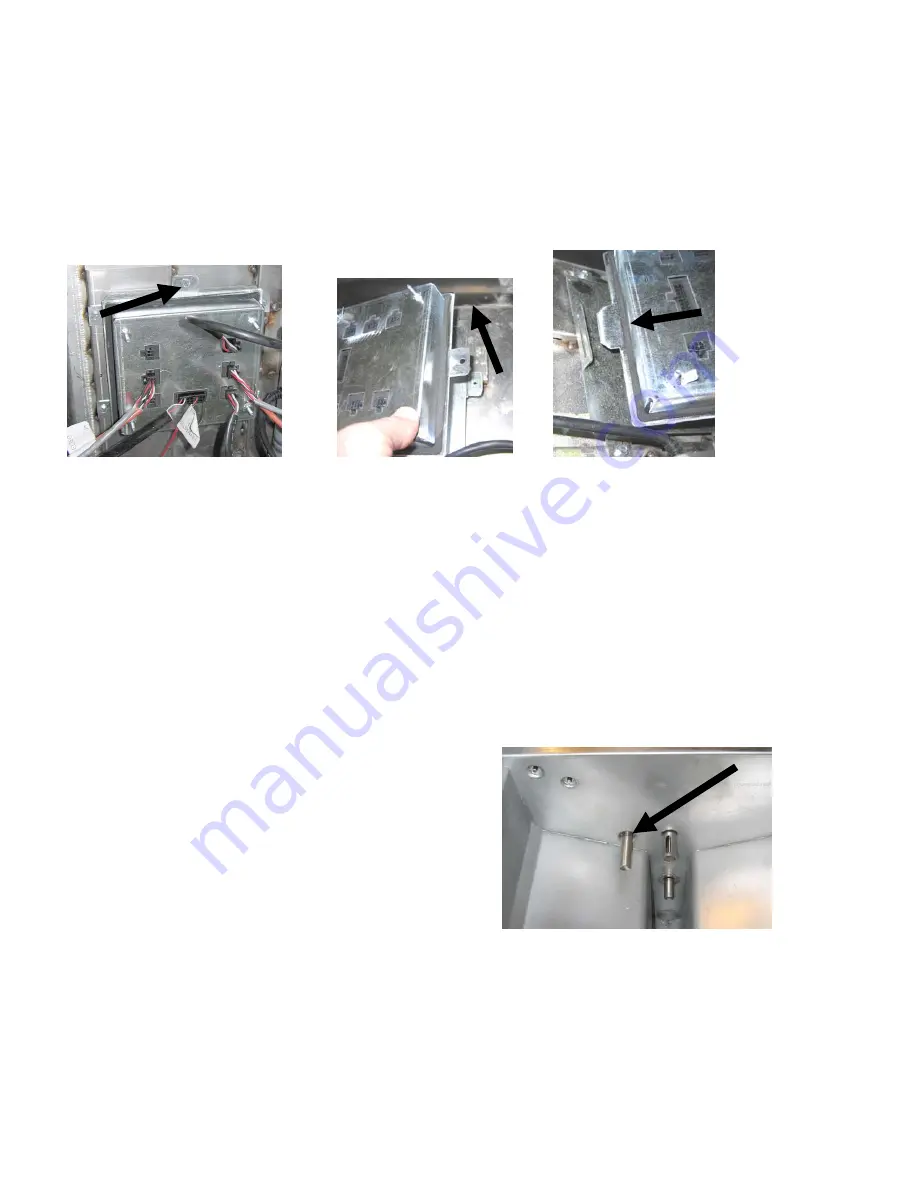
Mark and unplug the harnesses. The AIF board assembly is held in place with one screw (see Figure 16).
Remove the screw and the assembly drops down (see Figure 17) and the tab slides out of the bracket attached to
the frypot (see Figure 18). Reverse steps to reassemble, ensuring that the new AIF assembly slides into the slot
in the bracket. Once complete,
CYCLE POWER TO ENTIRE FRYER SYSTEM.
See section 1.15.6 to reset
control power. Check software version # and if necessary update the software. If a software update is
necessary, follow the instructions to update the software in section 1.19.
Figure
16
Figure
17
Figure 18
1.17.4 Replacing a Rotary Actuator
Disconnect the fryer from the electrical power supply.
Locate the actuator to be replaced and mark and
unplug the actuator. The actuators are held in place by two hex key screws. Loosen the 3/32” hex key
screws. It may be necessary to remove a gas line to the burner when removing a drain actuator. Remove
the actuator from the valve stem. Align the actuator with the valve stem and attach the new actuator.
Tighten the two hex key screws. Reconnect power and test the actuator.
NOTE:
Rotary actuators have two different part numbers and two different colors, which are mirror
images of each other that correspond to their mounting position.
1.17.5 Oil Level Sensor
The oil level sensor is a device that is used to prevent dry
firing of the frypot (see Figure 25). The sensor looks similar to
a high limit. The sensor is energized when the controller is
powered on with a soft on. The sensor heats up and detects the
oil around it. During filtration when the oil is drained, it senses
the difference between the oil and air.
It is controlled with a
board located next to the interface board (see Figure 26) and a
separate egg shaped plastic device (see Figure 27) that contains
additional electronics.
Use care when working with the sensor as temperatures may
reach as high as 500°F (260°C).
Figure 25
Содержание Frymaster FilterQuick 2FQG30U
Страница 8: ...1 3 ...
Страница 41: ...1 36 1 16 2 Bulk Wiring ...
Страница 56: ...1 51 1 18 6 Clogged Drain Failed Oil Sensor Error Flowchart ...
Страница 57: ...1 52 1 18 7 Menu Trees 1 18 7 1 FilterQuick Controller Setup Menu Tree ...
Страница 58: ...1 53 1 18 7 2 FilterQuick Filter and Info Mode Menu Tree ...
Страница 62: ...1 57 1 20 Principal Wiring Connections ...
Страница 63: ...1 58 1 21 Wiring Diagrams 1 21 1 Main FQG 230 430 120V CE Export ...
Страница 64: ...1 59 1 21 2 Main FQG 230 430 Australia ...
Страница 65: ...1 60 1 21 3 Main FQG 230 430 120V CE Export with Solid Shortening ...
Страница 66: ...1 61 1 21 4 Main FQG 230 430 Australia with Solid Shortening ...
Страница 67: ...1 62 1 21 5 Main FQG 330 530 120V CE Export ...
Страница 68: ...1 63 1 21 6 Main FQG 330 530 Australia ...
Страница 69: ...1 64 1 21 7 Main FQG 330 530 120V CE Export with Solid Shortening ...
Страница 70: ...1 65 1 21 8 Main FQG 330 530 Australia with Solid Shortening ...
Страница 71: ...1 66 1 21 9 Transformer Filter Box 430 530 ...
Страница 72: ...1 67 1 22 Simplified Wiring Diagrams 1 22 1 FilterQuick FQG30 Series Simplified Wiring with Push Pull Handles ...
Страница 73: ...1 68 1 22 2 FilterQuick FQG30 Series Simplified Wiring with Push Buttons ...
Страница 74: ...1 69 1 22 3 FilterQuick FQG30 Series Data Network Flowchart ...
Страница 76: ...1 71 1 24 Shortening Melting Unit Wiring Diagram ...
Страница 77: ...1 72 1 25 Modular Basket Lift Wiring Diagram 100 120V 1 2 4 3 5 6 12 7 8050518E ...
Страница 79: ...1 74 1 27 Basket Lift Interface Harness ...


