1-23
If 24 VAC is present across gas valve main coil, check the incoming gas pressure and compare to the tables
on page 2-4 of the Installation and Operation manual.
1.
If incoming gas pressure
is not
correct, the probable cause is a problem with the gas supply to fryer.
2.
If incoming gas pressure
is
correct, check the burner manifold gas pressure and compare it to the tables
on page 2-7 of the Installation and Operation manual.
a.
If burner manifold gas pressure
is
not
correct, the probable cause is an improperly adjusted or failed
gas valve. Adjust the valve by following the procedure “Check Burner Manifold Pressure” in
Section 1.4 of this manual. If the valve cannot be adjusted, replace it.
b. If outgoing gas pressure
is
correct, the gas valve is okay.
1.11.3 Troubleshooting the Temperature Probe
CAUTION
Disconnect the FILTERQUICK™ controller before testing temperature probe
resistances to avoid invalid readings
Prior to checking for problems associated with the temperature probe, inspect the probe body for damage while
it is still in the frypot. Remove and replace the probe if it is bent, dented, or cracked. Also, inspect leads for
fraying, burning, breaks, and/or kinks. If found, replace the probe.
The following processes will assist you in troubleshooting the gas valve and ruling it out as a probable cause:
Before testing the probe, determine the temperature the cooking oil using another thermometer or pyrometer
placed at the tip of the questionable probe.
If resistance through J3 pins 2 and 6 (J1 pins 2 and 6 for left side of dual unit) is not approximately
equal to that given in the Probe Resistance Chart for the corresponding temperature, the probe has
failed and must be replaced.
If resistance through J3 pins 2 and 6 (J1 pins 2 and 6 for left side of dual unit) is approximately equal
to that given in the Probe Resistance Chart for the corresponding temperature, measure the
resistance through each of the previously tested pins to ground.
1.
If resistance
is not
5 mega-Ohms or greater in each pin, the probe has failed and must be replaced.
2.
If resistance
is
5 mega-Ohms or greater in each pin, the probe is okay.
1.11.4 Replacing the Transformer or Filter, or Reset Switch Relay
Disconnect the fryer from the electrical power supply. Remove the cover from the transformer box in the rear
of the fryer to expose the interior of the transformer box (see photo below). Replace the transformer or filter
relay marking the wires to ease reassembly. Once replaced, reconnect the power. When replacing a filter relay
in the transformer, ensure the 24VDC relay (8074482) is used.
Содержание Frymaster FilterQuick 2FQG30U
Страница 8: ...1 3 ...
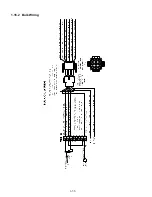
Страница 41: ...1 36 1 16 2 Bulk Wiring ...
Страница 56: ...1 51 1 18 6 Clogged Drain Failed Oil Sensor Error Flowchart ...
Страница 57: ...1 52 1 18 7 Menu Trees 1 18 7 1 FilterQuick Controller Setup Menu Tree ...
Страница 58: ...1 53 1 18 7 2 FilterQuick Filter and Info Mode Menu Tree ...
Страница 62: ...1 57 1 20 Principal Wiring Connections ...
Страница 63: ...1 58 1 21 Wiring Diagrams 1 21 1 Main FQG 230 430 120V CE Export ...
Страница 64: ...1 59 1 21 2 Main FQG 230 430 Australia ...
Страница 65: ...1 60 1 21 3 Main FQG 230 430 120V CE Export with Solid Shortening ...
Страница 66: ...1 61 1 21 4 Main FQG 230 430 Australia with Solid Shortening ...
Страница 67: ...1 62 1 21 5 Main FQG 330 530 120V CE Export ...
Страница 68: ...1 63 1 21 6 Main FQG 330 530 Australia ...
Страница 69: ...1 64 1 21 7 Main FQG 330 530 120V CE Export with Solid Shortening ...
Страница 70: ...1 65 1 21 8 Main FQG 330 530 Australia with Solid Shortening ...
Страница 71: ...1 66 1 21 9 Transformer Filter Box 430 530 ...
Страница 72: ...1 67 1 22 Simplified Wiring Diagrams 1 22 1 FilterQuick FQG30 Series Simplified Wiring with Push Pull Handles ...
Страница 73: ...1 68 1 22 2 FilterQuick FQG30 Series Simplified Wiring with Push Buttons ...
Страница 74: ...1 69 1 22 3 FilterQuick FQG30 Series Data Network Flowchart ...
Страница 76: ...1 71 1 24 Shortening Melting Unit Wiring Diagram ...
Страница 77: ...1 72 1 25 Modular Basket Lift Wiring Diagram 100 120V 1 2 4 3 5 6 12 7 8050518E ...
Страница 79: ...1 74 1 27 Basket Lift Interface Harness ...


