


1-26
1.13 Probe Resistance Chart
Probe Resistance Chart
For use with FilterQuick™ Series fryers manufactured with Minco Thermistor probes only.
F OHMS C F OHMS C F OHMS C F OHMS C F OHMS C
60 1059 16
130 1204
54 200 1350
93
270 1493 132
340 1634 171
65 1070 18
135 1216
57 205 1361
96
275 1503 135
345 1644 174
70 1080 21
140 1226
60 210 1371
99
280 1514 138
350 1654 177
75 1091 24
145 1237
63
215 1381 102
285 1524 141
355 1664 179
80 1101 27
150 1247
66
220 1391 104
290 1534 143
360 1674 182
85 1112 29
155 1258
68
225 1402 107
295 1544 146
365 1684 185
90 1122 32
160 1268
71
230 1412 110
300 1554 149
370 1694 188
95 1133 35
165 1278
74
235 1422 113
305 1564 152
375 1704 191
100 1143 38 170 1289
77
240 1432 116
310 1574 154
380 1714 193
105 1154 41 175 1299
79
245 1442 118
315 1584 157
385 1724 196
110 1164 43 180 1309
82
250 1453 121
320 1594 160
390 1734 199
115 1174 46 185 1320
85
255 1463 124
325 1604 163
395 1744 202
120 1185 49 190 1330
88
260 1473 127
330 1614 166
400 1754 204
125 1195 52 195 1340
91
265 1483 129
335 1624 168
405 1764 207
1.14 ATO (Automatic Top-off) Service Procedures
The automatic top-off system is activated when the oil level falls below a sensor in the front of the frypot. The
signal is sent to the ATO board to engage the return actuator to the frypot and turn on the ATO pump. The
pump draws oil from the JIB (Jug In Box) through the rear return manifold into the rear of the frypot. Once the
oil level has satisfied the sensor, the pump turns off and the actuator closes.
The ATO board is located inside the box, behind the JIB (see Figure 1). The
power for the ATO board is supplied from the transformer box. The power
passes through the transformer inside the ATO box to the board.
Figure 1
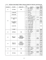
1.14.1 ATO (Automatic Top-Off) Troubleshooting
Problem
Probable Causes
Corrective Action
Fryer tops off cold.
Incorrect setpoint.
Ensure setpoint is correct.
No power to ATO board
A.
J5 connection unplugged
B.
Fuse blown.
C.
Transformer malfunction
A.
Check to ensure J5 on front of ATO board
is fully locked into connector.
B.
Ensure fuse located on right side of ATO
box is not blown.
C.
Check that proper voltage is present at
transformer. See table in section 1.13.2.
One vat tops off but
other vats fail to top off.
A.
Loose wire connection.
B.
Actuator issue.
A.
Ensure all wiring harnesses are securely
connected to ATO board and solenoids.
B.
Check return actuator to ensure actuator
is functional.
Содержание Frymaster FilterQuick 2FQG30U
Страница 8: ...1 3 ...
Страница 41: ...1 36 1 16 2 Bulk Wiring ...
Страница 56: ...1 51 1 18 6 Clogged Drain Failed Oil Sensor Error Flowchart ...
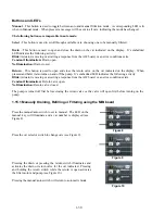
Страница 57: ...1 52 1 18 7 Menu Trees 1 18 7 1 FilterQuick Controller Setup Menu Tree ...
Страница 58: ...1 53 1 18 7 2 FilterQuick Filter and Info Mode Menu Tree ...
Страница 62: ...1 57 1 20 Principal Wiring Connections ...
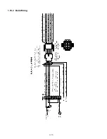
Страница 63: ...1 58 1 21 Wiring Diagrams 1 21 1 Main FQG 230 430 120V CE Export ...
Страница 64: ...1 59 1 21 2 Main FQG 230 430 Australia ...
Страница 65: ...1 60 1 21 3 Main FQG 230 430 120V CE Export with Solid Shortening ...
Страница 66: ...1 61 1 21 4 Main FQG 230 430 Australia with Solid Shortening ...
Страница 67: ...1 62 1 21 5 Main FQG 330 530 120V CE Export ...
Страница 68: ...1 63 1 21 6 Main FQG 330 530 Australia ...
Страница 69: ...1 64 1 21 7 Main FQG 330 530 120V CE Export with Solid Shortening ...
Страница 70: ...1 65 1 21 8 Main FQG 330 530 Australia with Solid Shortening ...
Страница 71: ...1 66 1 21 9 Transformer Filter Box 430 530 ...
Страница 72: ...1 67 1 22 Simplified Wiring Diagrams 1 22 1 FilterQuick FQG30 Series Simplified Wiring with Push Pull Handles ...
Страница 73: ...1 68 1 22 2 FilterQuick FQG30 Series Simplified Wiring with Push Buttons ...
Страница 74: ...1 69 1 22 3 FilterQuick FQG30 Series Data Network Flowchart ...
Страница 76: ...1 71 1 24 Shortening Melting Unit Wiring Diagram ...
Страница 77: ...1 72 1 25 Modular Basket Lift Wiring Diagram 100 120V 1 2 4 3 5 6 12 7 8050518E ...
Страница 79: ...1 74 1 27 Basket Lift Interface Harness ...