


1-35
1.15.6 Control Power Reset Switch
The control power reset switch, is a momentary
rocker switch located below the left control box
(see Figures 14), that resets all power to all the
controllers and boards in the fryer. It is
necessary to reset all power after replacing any
controller or board. Press and hold the switch
for at least ten seconds when resetting the
control power to ensure power has sufficiently
drained from boards.
Figure 14
1.16 Bulk Oil Service Issues
1.16.1 Bulk MIB Tests
Bulk oil providers provide waste and/or fresh bulk oil services.
The FilterQuick
™
fryer will ONLY operate with bulk oil systems that have a three-pole float
switch. If the float switch is the older two-pole switch, call the bulk oil provider. These float
switches are polarity specific which may short to ground and damage an MIB board.
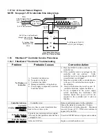
Normal measurements (MIB J6 8-pin connector with everything connected)
AC voltage measurements:
Pin 1 to Pin 2 - 24 VAC.
Pin 2 to Pin 8 - 24 VAC when waste tank is full, 0 VAC when it is not full.
Pin 1 to Pin 3 - 24 VAC when bulk fresh oil add switch and pump is on, 0 VAC when it is off.
Using the Bulk test box, PN# 108-0716 allows a quick and easy way to check the 24VAC, the waste full switch
and when the bulk fresh oil pump is operating.
Troubleshooting
All return and drain valves should be closed and pump should be off while the MIB is resetting. If any of the
valves or the pump is on during reset, the MIB board is bad or wires are shorted.
Bulk fresh oil pump is not operating or JIB is not filling:
See page 1-38 to ensure that no other function is taking priority over adding oil to jug.
1. Reset the power; wait 60 seconds and see if the valve opens.
With the JIB button pressed:
2. Voltage at MIB board from Pin 1 to Pin 2 should be 24 VAC; if not, check connections from bulk fresh oil
pump 24VAC transformer and check transformer.
3. Voltage at MIB board from Pin 1 to Pin 3 should be 24 VAC when filling JIB or vat; if not, the MIB board is
bad or wires to pump relay are shorted or both.
4. Voltage at Add pump relay should be 24 VAC; if not, check wiring from MIB board. The relay should be
located at the fresh oil tank pump system.
5. Check voltage at ATO board on J8. Pin 9 to Pin 1 should be 24 VAC with the orange button pressed.
Waste full signal:
Pin 2 to Pin 8 should be 24 VAC when full, 0 VAC when not full; if no voltage level change, the connection from
bulk waste oil switch or MIB board is bad.
Содержание Frymaster FilterQuick 2FQG30U
Страница 8: ...1 3 ...
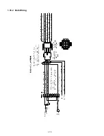
Страница 41: ...1 36 1 16 2 Bulk Wiring ...
Страница 56: ...1 51 1 18 6 Clogged Drain Failed Oil Sensor Error Flowchart ...
Страница 57: ...1 52 1 18 7 Menu Trees 1 18 7 1 FilterQuick Controller Setup Menu Tree ...
Страница 58: ...1 53 1 18 7 2 FilterQuick Filter and Info Mode Menu Tree ...
Страница 62: ...1 57 1 20 Principal Wiring Connections ...
Страница 63: ...1 58 1 21 Wiring Diagrams 1 21 1 Main FQG 230 430 120V CE Export ...
Страница 64: ...1 59 1 21 2 Main FQG 230 430 Australia ...
Страница 65: ...1 60 1 21 3 Main FQG 230 430 120V CE Export with Solid Shortening ...
Страница 66: ...1 61 1 21 4 Main FQG 230 430 Australia with Solid Shortening ...
Страница 67: ...1 62 1 21 5 Main FQG 330 530 120V CE Export ...
Страница 68: ...1 63 1 21 6 Main FQG 330 530 Australia ...
Страница 69: ...1 64 1 21 7 Main FQG 330 530 120V CE Export with Solid Shortening ...
Страница 70: ...1 65 1 21 8 Main FQG 330 530 Australia with Solid Shortening ...
Страница 71: ...1 66 1 21 9 Transformer Filter Box 430 530 ...
Страница 72: ...1 67 1 22 Simplified Wiring Diagrams 1 22 1 FilterQuick FQG30 Series Simplified Wiring with Push Pull Handles ...
Страница 73: ...1 68 1 22 2 FilterQuick FQG30 Series Simplified Wiring with Push Buttons ...
Страница 74: ...1 69 1 22 3 FilterQuick FQG30 Series Data Network Flowchart ...
Страница 76: ...1 71 1 24 Shortening Melting Unit Wiring Diagram ...
Страница 77: ...1 72 1 25 Modular Basket Lift Wiring Diagram 100 120V 1 2 4 3 5 6 12 7 8050518E ...
Страница 79: ...1 74 1 27 Basket Lift Interface Harness ...