1-8
5.
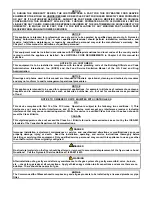
Reverse the procedure to install the replacement board, being sure that the spacers behind the board are in
place and the controller locator wire is attached to a stud.
1.9.4 Replacing an Ignition Module
1.
Disconnect the fryer from the electrical supply.
2.
Open the control panel by removing the screws on the bottom of the bezel. Carefully lower the bezel.
3.
Remove the top two screws in the upper corners of the controller.
4.
Swing the controller out from the top and allow it to rest on its hinge tabs.
5.
Remove the two screws attaching the module cover.
6.
Loosen the nuts attached to the screws of the module. Slide the module towards the rear of the component
box until the nuts drop through the keyholes.
7.
Carefully rotate the module and pull forward. On some units it may be necessary to remove the blower.
8.
Disconnect the wires from the ignition module, marking or making a note of the wires and terminals to
facilitate reconnection.
9.
Remove the screws from the module.
10.
Move the screws and spacers to the new module.
11.
Reverse the procedure to install the replacement module.
1.9.5 Replacing an Ignitor Assembly
DANGER
Drain the frypot before proceeding further.
1.
Disconnect the fryer from the electrical supply.
2.
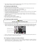
Disconnect the flame sensor wire by carefully pulling its push-on terminal from the terminal strip on the
ignitor. Disconnect the gas enrichment tube at the ignitor-end compression fitting. Disconnect the ignition
cable from the ignitor by grasping its boot and gently pulling toward you. (See photo on the next page)
3.
Remove the sheet metal screws securing the ignitor to the mounting plate and pull the ignitor from the fryer.
4.
Reverse the procedure to install the replacement ignitor.
1.9.6 Replacing or Cleaning a Combustion Air Blower
1.
Disconnect the blower wiring harness, remove the blower assembly mounting nuts, and remove the blower
assembly from the fryer. If cleaning the motor, continue with Step 2; otherwise, install the replacement
blower, reconnect the wiring harness, and then go to Step 6.
Flame Sensor Wire
Gas Enrichment Tube
Ignition Cable
Содержание Frymaster FilterQuick 2FQG30U
Страница 8: ...1 3 ...
Страница 41: ...1 36 1 16 2 Bulk Wiring ...
Страница 56: ...1 51 1 18 6 Clogged Drain Failed Oil Sensor Error Flowchart ...
Страница 57: ...1 52 1 18 7 Menu Trees 1 18 7 1 FilterQuick Controller Setup Menu Tree ...
Страница 58: ...1 53 1 18 7 2 FilterQuick Filter and Info Mode Menu Tree ...
Страница 62: ...1 57 1 20 Principal Wiring Connections ...
Страница 63: ...1 58 1 21 Wiring Diagrams 1 21 1 Main FQG 230 430 120V CE Export ...
Страница 64: ...1 59 1 21 2 Main FQG 230 430 Australia ...
Страница 65: ...1 60 1 21 3 Main FQG 230 430 120V CE Export with Solid Shortening ...
Страница 66: ...1 61 1 21 4 Main FQG 230 430 Australia with Solid Shortening ...
Страница 67: ...1 62 1 21 5 Main FQG 330 530 120V CE Export ...
Страница 68: ...1 63 1 21 6 Main FQG 330 530 Australia ...
Страница 69: ...1 64 1 21 7 Main FQG 330 530 120V CE Export with Solid Shortening ...
Страница 70: ...1 65 1 21 8 Main FQG 330 530 Australia with Solid Shortening ...
Страница 71: ...1 66 1 21 9 Transformer Filter Box 430 530 ...
Страница 72: ...1 67 1 22 Simplified Wiring Diagrams 1 22 1 FilterQuick FQG30 Series Simplified Wiring with Push Pull Handles ...
Страница 73: ...1 68 1 22 2 FilterQuick FQG30 Series Simplified Wiring with Push Buttons ...
Страница 74: ...1 69 1 22 3 FilterQuick FQG30 Series Data Network Flowchart ...
Страница 76: ...1 71 1 24 Shortening Melting Unit Wiring Diagram ...
Страница 77: ...1 72 1 25 Modular Basket Lift Wiring Diagram 100 120V 1 2 4 3 5 6 12 7 8050518E ...
Страница 79: ...1 74 1 27 Basket Lift Interface Harness ...


