EUROBLOC
SERVICE MANUAL FOR HOIST
29/212
This document and the information contained herein, is the exclusive property of Verlinde S.A.S. and represents a non-public, confidential and proprietary trade secret that
may not be reproduced, disclosed to third parties, altered or otherwise employed in any manner whatsoever without the express written consent of Verlinde S.A.S.
Copyright © (2013) Verlinde S.A.S. All rights reserved.
06/2015
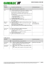
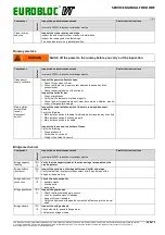
Component
In
te
rv
a
l
Inspection and maintenance task
Interval is SWP% reduction or calendar months
See further instructions
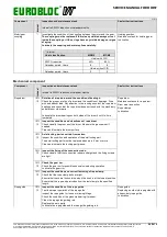
Contactors
Control
warning
12
Check that all the movements are operational in the hoist, in the
trolley and in the bridge.
Check visually that the contactors are clean and there are no visible
damages.
Contactors
Condition
monitoring unit
warning “Control"
When the condition monitoring unit indicates the “Control” warning, one of
the start counters 2-7 (ST up), 2-8 (ST down) or 2-9 (ST fast), has
reached the set design limit (the default value is 640,000 operations)
which is defined with parameter 6-19 (Max Control) that calculates the life-
time of the contactors.
When the design limit has been reached, replace the contactors (Up,
Down, Slow, Fast and Brake Contactors). If a brake contactor contains an
auxiliary contact block or a time delay auxiliary contact block, replace that
part as well.
After the replacement, calculate a new value for parameter 6-19. See
instructions in chapter “Contactors”.
If the condition monitoring unit is not used with the hoist, replace the
contactors after six years of operation according to the designed duty
cycle.
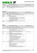
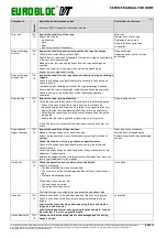
Over-current
protectors
10%
12
Check the adjustment of the over-current protectors.
Fuses
10%
12
Inspect visually that the fuse holder and the fuses are clean and
there are no visible damages.
Check the correct amperage rating.
Braking resistors
(with some
frequency
converter models)
10%
12
Clean all dust or dirt from the braking resistors.
Hoisting
frequency
converter
10%
12
Check that wires are securely fastened.
Check fault code records.
Inspect the operation and cleanliness of the cooling fan.
See further instructions in the
equipment-specific “Service Manual
for Frequency Control System”
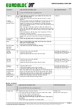
Traveling
frequency
converter
10%
12
Check that wires are securely fastened.
Check fault code records.
Inspect the operation and cleanliness of the cooling fan.
See further instructions in the
equipment-specific “Service Manual
for Frequency Control System”
Frequency
controller
10%
12
Check fault code records.
Verify that the frequency converter fan is working.
Check that the frequency drive is clean from dust or dirt.
See further instructions in the
equipment-specific “Service Manual
for Frequency Control System”.
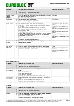
VARIATOR LM /
VARIATOR LA2
Condition
monitoring unit
warning “Control”
When the condition monitoring unit indicates the “Control” warning, the
design limit (the default value is 640,000 operations) has been reached.
Replace the brake timer block, the brake contactor as well as the brake
control PC board that contains the brake relay (in VARIATOR LM /
VARIATOR LA2 frequency converters, replace the B board).
Radio receiver
10%
12
Check that the radio receiver is working normally.
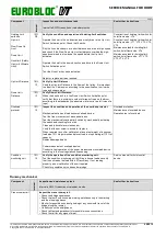
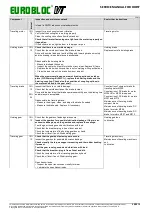
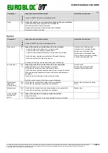
Motors and gears
Component
In
te
rv
a
l
Inspection and maintenance task
Interval is SWP% reduction or calendar months
See further instructions
Hoisting motor
10%
12
Inspect for any unusual noise or vibration.
Drive and check that the hoisting motor operates properly when loaded.
Verify that the cooling fan is working properly.
Clean the cooling ribs surface from dust and dirt.
Check that all motor fastenings are tight and the motor is properly on
its position.
If the bolts are loose, tighten them to the proper torque.
Hoisting motor
Maintenance of hoisting motor

