EUROBLOC
SERVICE MANUAL FOR HOIST
48/212
This document and the information contained herein, is the exclusive property of Verlinde S.A.S. and represents a non-public, confidential and proprietary trade secret that
may not be reproduced, disclosed to third parties, altered or otherwise employed in any manner whatsoever without the express written consent of Verlinde S.A.S.
Copyright © (2013) Verlinde S.A.S. All rights reserved.
06/2015
3
4
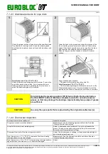
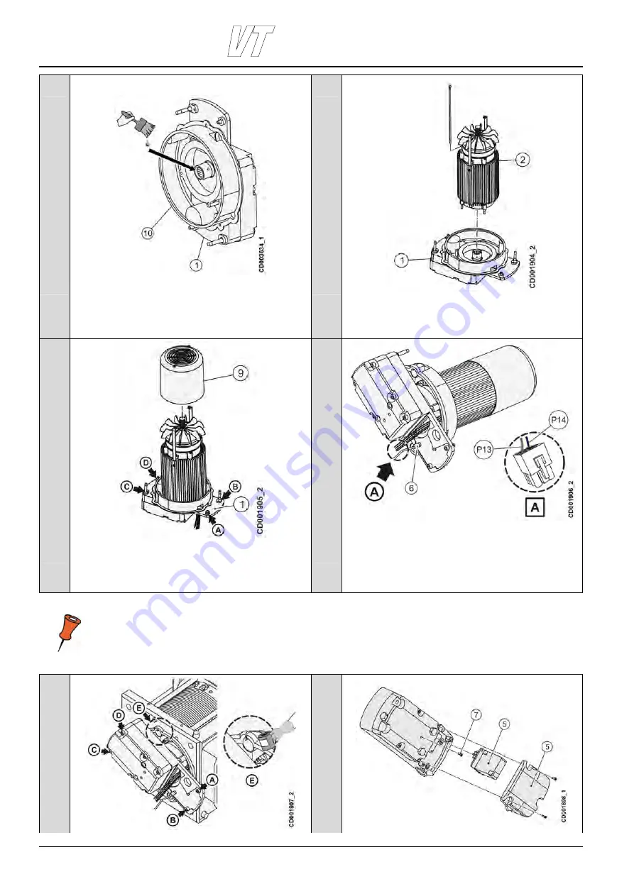
Grease the motor side coupling teeth after the coupling is
installed.
Install the grease cover (10) to the gearbox (1) with three
screws.
Lift the hoisting motor (2) above the gearbox. Pass the power
cables and the brake cable through the holes in the hoisting
gear
5
6
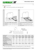
Ensure the motor shaft engages with the coupling and the
screw holes align. Install the four mounting screws (A, B, C
and D) and washers to the gearbox (1). Tighten them to the
recommended torque (see “Appendix: tightening torques”).
Reassemble the fan cover (9) with screws.
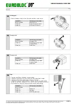
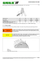
Tighten the bushing (6) on the brake cable. Insert the brake
cable wires into the connector (A).
Pin 13 (P13) = Brown wire
Pin 14 (P14) = Blue wire
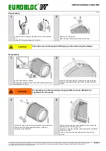
Note: When hoisting motor is placed check the installation by checking the hoisting motor and gear joint. The
faces of joint must be completely attached to each other.
7
8

