EUROBLOC
SERVICE MANUAL FOR HOIST
62/212
This document and the information contained herein, is the exclusive property of Verlinde S.A.S. and represents a non-public, confidential and proprietary trade secret that
may not be reproduced, disclosed to third parties, altered or otherwise employed in any manner whatsoever without the express written consent of Verlinde S.A.S.
Copyright © (2013) Verlinde S.A.S. All rights reserved.
06/2015
3
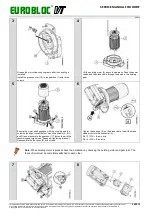
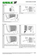
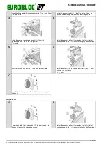
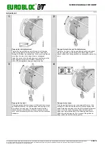
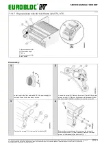
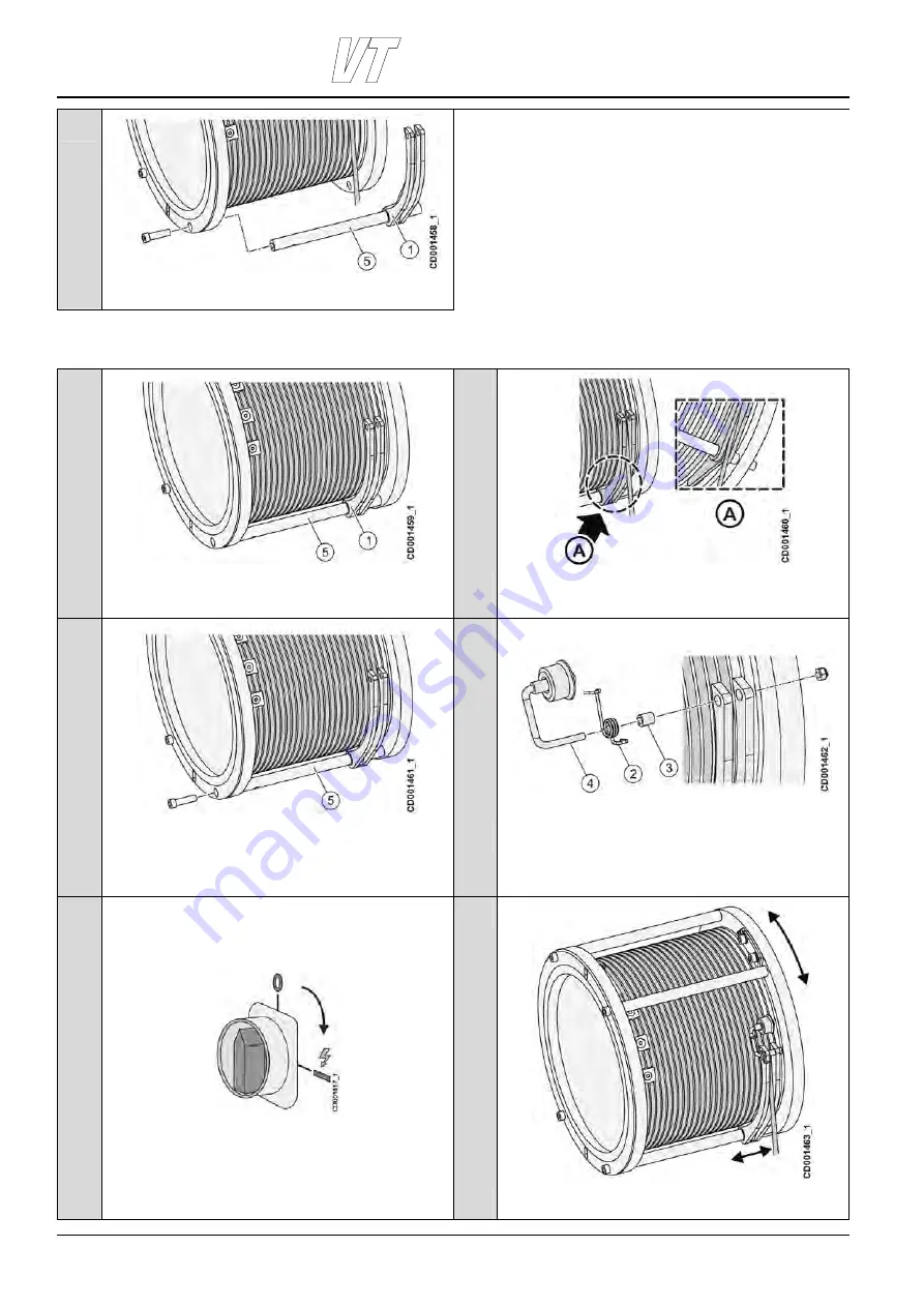
Remove the bolts in order to remove the connector rod (5)
along with the rope guide (1).
Reassembly
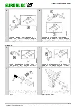
1
2
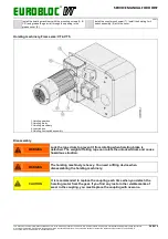
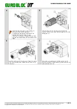
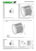
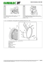
Insert the connector rod (5) into the rope guide (1). Install the
connector rod (5) with the rope guide (1) on the drum.
Place the rope guide so that the rope passes through the slot
in the rope guide and the guiding surface of the rope guide
sits in the groove next to the last rope wrap on the drum.
3
4
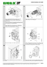
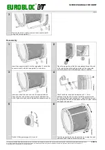
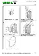
Insert one side of the connector rod (5) loosely with bolts.
Place the other end of the connector rod (5) and insert the
bolts. Tighten the bolts on both sides of the connector rod (5).
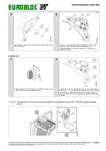
Check that there is operational clearance of 1…2 mm
between the guide and the ropes. Install the pressure roller
(4), roller spring (2), and roller axle (3). Install first one loop of
the spring and turn after that the second loop into place. Install
and tighten the axle bolt.
5
6
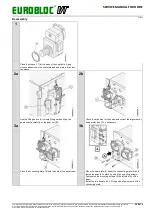
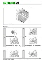
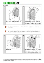
Switch ON the power supply to the hoist.
Test the rope guide for smooth operation by running the hoist
both directions. Install the machinery covers.

