EUROBLOC
SERVICE MANUAL FOR HOIST
109/212
This document and the information contained herein, is the exclusive property of Verlinde S.A.S. and represents a non-public, confidential and proprietary trade secret that
may not be reproduced, disclosed to third parties, altered or otherwise employed in any manner whatsoever without the express written consent of Verlinde S.A.S.
Copyright © (2013) Verlinde S.A.S. All rights reserved.
06/2015
3
4
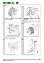
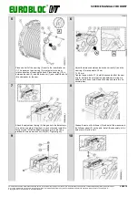
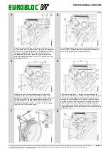
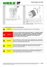
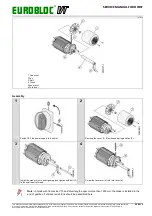
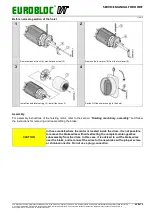
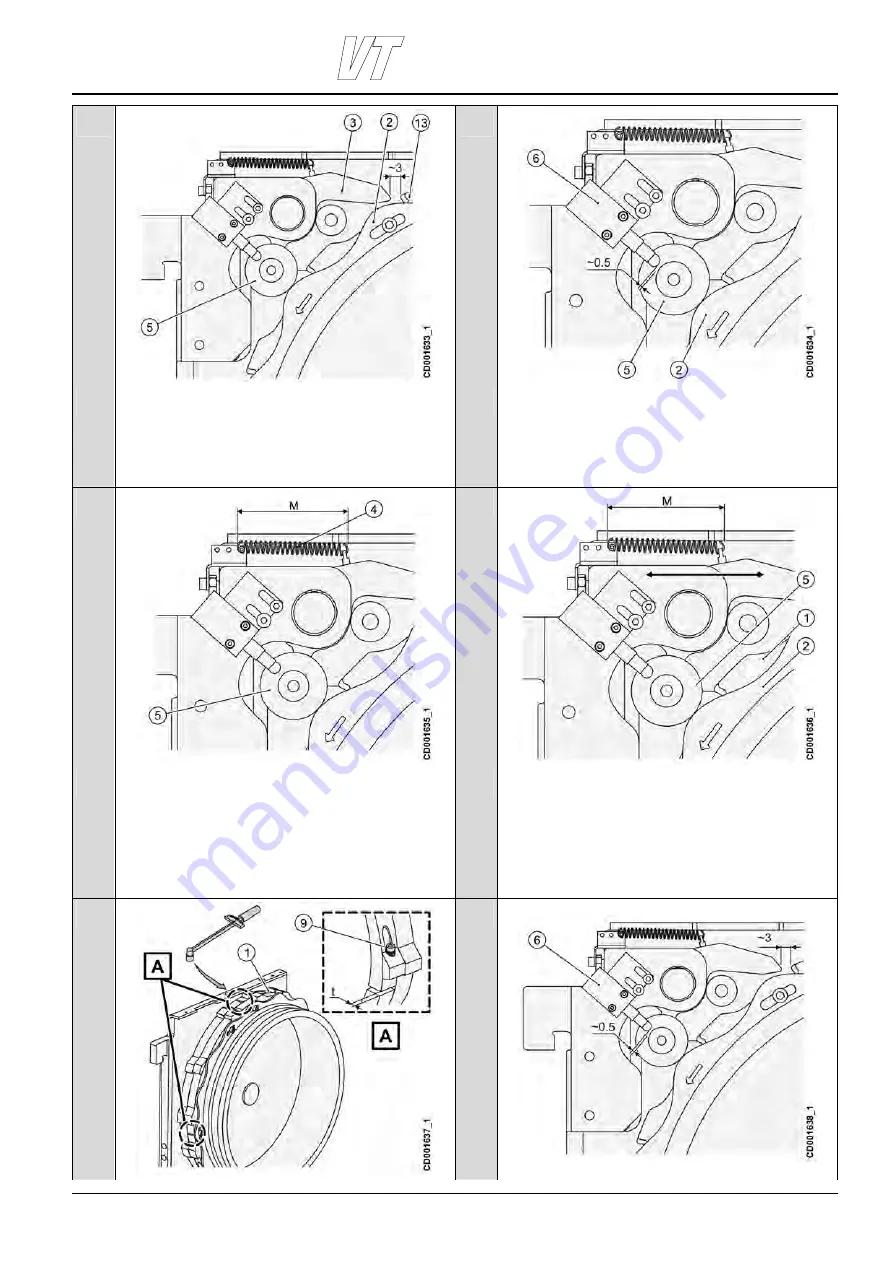
Adjust the cam wheel (2) so that when the follower roll (5) is
on the highest point of the cam wheel (2) there is a clearance
of 3 mm (0.12 ”) between the head of the detent arm (3) and
the tooth of the brake rim (13). If the cam wheel (2) is
replaced, position the cam wheel (2) by turning it until the
distance between the brake rim teeth (13) and the cam ring
wave peak is 36 mm.
Adjust the gap between the limit switch (6) and the roll (5) to
0.5 mm (0.02”). Make this adjustment when the follower roll
(5) is on the highest level of the cam wheel (2).
5
6
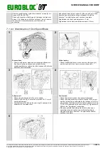
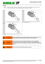
Adjust the length M of the helical spring (4) to the value
recorded on the drum brake report that is included in the
delivered hoist documentation. The follower roll (5) must be at
the highest point on the cam wheel when the length of the
spring is measured. Be aware that the spring must not be
damaged. If damaged, replace the spring. Verify the spring
type from the Q drum brake report.
Verify that the brake rim (1) screws are loose allowing the
brake rims to slide freely on the drum during the following test.
Test that the overspeed drum brake does not actuate when
lowering the nominal load with full speed. If the drum brake
activates, increase the M dimension to increase the follower
roll (5) tension on the cam wheel (2) preventing premature
drum braking action. Before repeating the test, verify that all
rim and cam wheel (2) positioning marks are correct according
to steps 3, 4 and 5.
7
8

