EUROBLOC
SERVICE MANUAL FOR HOIST
91/212
This document and the information contained herein, is the exclusive property of Verlinde S.A.S. and represents a non-public, confidential and proprietary trade secret that
may not be reproduced, disclosed to third parties, altered or otherwise employed in any manner whatsoever without the express written consent of Verlinde S.A.S.
Copyright © (2013) Verlinde S.A.S. All rights reserved.
06/2015
Limits for the wear of the brake splines on motor shaft
Motor
MF10
MF11
MF13
Module [mm]
1.25
1.25
1.25
Number of teeth
18
26
26
New Wn max [mm]
13.48
17.35
17.35
New Wn min [mm]
13.46
17.32
17.32
Change limit in GO Wn [mm]
13.4
17.2
17.2
Final rejection limit Wn [mm]
13.3
17.1
17.1
Number of teeth in measurement Wn
4
5
5
Limits for the wear of the coupling splines on motor and gear shaft
Motor
MF10
MF11
MF13
MF13
Module [mm]
1.0
1.5
1.5
2.0
Number of teeth
23
18
21
18
New Wn max [mm]
7.66
6.98
11.47
15.23
New Wn min [mm]
7.62
6.94
11.43
15.19
Change limit in GO Wn [mm]
7.5
6.7
11.2
15.0
Final rejection limit Wn [mm]
7.4
6.5
11.0
14.8
Number of teeth in measurement Wn
3
2
3
3
After the replacement, reset the hoisting brake SWP value by setting parameter 7-24 (Br Count) to zero (0).”
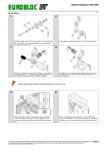
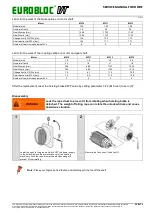
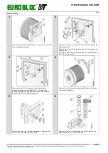
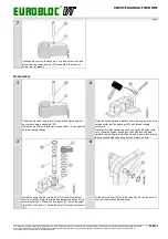
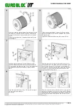
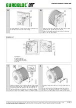
Disassembly
WARNING
Lock the rope drum to prevent it from rotating when hoisting brake is
detached. The weight of falling rope can rotate the unlocked drum and cause
hazardous situation.
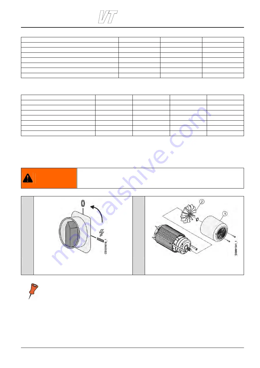
1
2
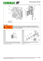
Lower the hook to the ground. Switch OFF the power supply
to the hoist. Remove the protective cover of the hoisting
machinery. Lock the rope drum with a wooden wedge to
prevent it from rotating.
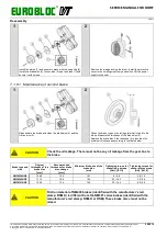
Remove the fan cover (1) and fan (2).
Note: Place your fingers behind the fan and carefully pull the fan off the shaft.

