EUROBLOC
SERVICE MANUAL FOR HOIST
50/212
This document and the information contained herein, is the exclusive property of Verlinde S.A.S. and represents a non-public, confidential and proprietary trade secret that
may not be reproduced, disclosed to third parties, altered or otherwise employed in any manner whatsoever without the express written consent of Verlinde S.A.S.
Copyright © (2013) Verlinde S.A.S. All rights reserved.
06/2015
1
2
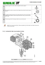
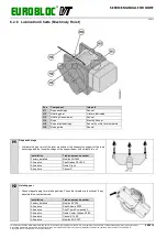
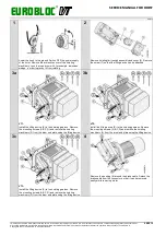
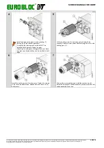
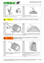
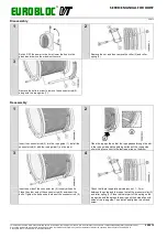
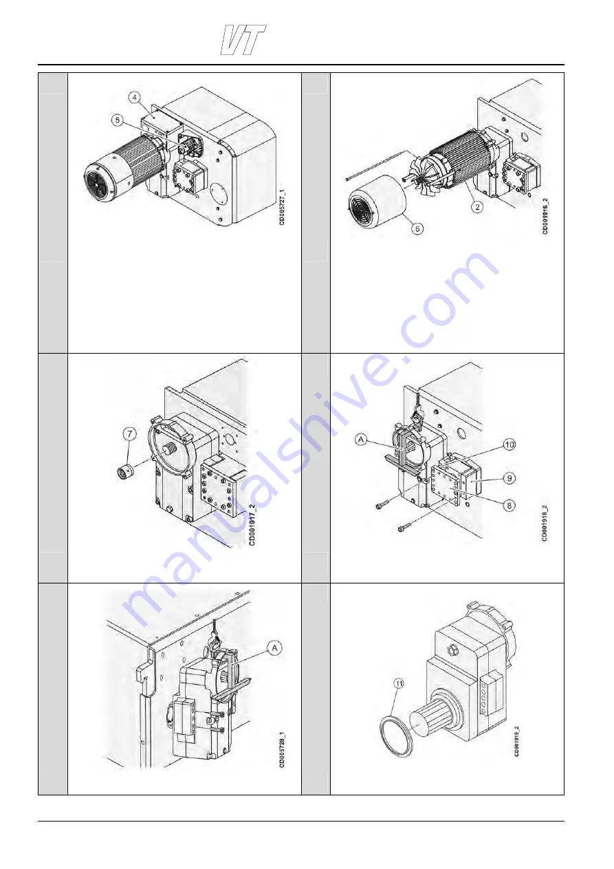
If you must disassemble both the hoisting motor and the
hoisting gearbox from the drum assembly, start by
disassembling the junction box and the cabling inside the
junction box (4).
If you must disassemble the hoisting limit switch assembly (5),
open first the switch cover and disassemble the wiring, before
removing the whole limit switch assembly.
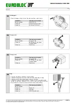
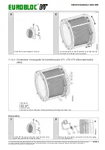
If you disassemble only the hoisting motor, it is possible to
detach only the motor part and pull out some of the motor
cabling, without disassembling the junction box.
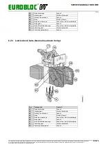
Remove fan cover (6). Remove the motor (2) by removing the
screws holding it to the hoisting gear.
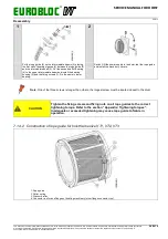
3
4a
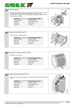
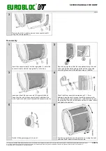
Remove the coupling (7) on the reducer gear shaft.
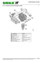
Attach the lifting device (A) and remove the mounting screws,
the connecting plate (8), and shim plate (9). Remove also the
two dowel pins (10) along with the connecting plate.
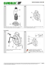
4b
5
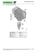
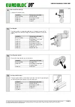
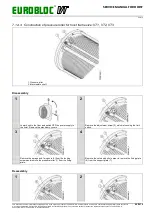
Remove the mounting screws also from the left side of the
gear.
Remove the sleeve (11) from the hoisting gear axle, in case it
remains there after removing the gearbox with a lifting device.

