


262
Configuration Examples
EdgeSwitch
™
Administration Guide
Ubiquiti Networks, Inc.
Configuring Multiple Spanning Tree Protocol
This example shows how to enable IEEE 802.1s Multiple Spanning Tree (MST) protocol on the switch and all
of the ports and to set the bridge priority.
To make multiple switches be part of the same MSTP region, make sure the Force Protocol Version setting for
all switches is IEEE 802.1s. Also, make sure the configuration name, digest key, and revision level are the same
for all switches in the region.
Note:
The digest key is generated based on the association of VLANs to different instances. To ensure
the digest key is same, the mapping of VLAN to instance must be the same on each switch in the
region. For example, if VLAN 10 is associated with instance 10 on one switch, you must associate VLAN
10 and instance 10 on the other switches.
Using the Web UI to Configure MSTP
1. Create VLANs 10 and 20.
a. Access the
Switching
>
VLAN
>
Status
page.
b. Click
Add
to create a VLAN.
c. Select the
VLAN ID-Individual
option and enter
10
.
d. Click
Submit
.
e. Repeat the steps to add VLAN 20.
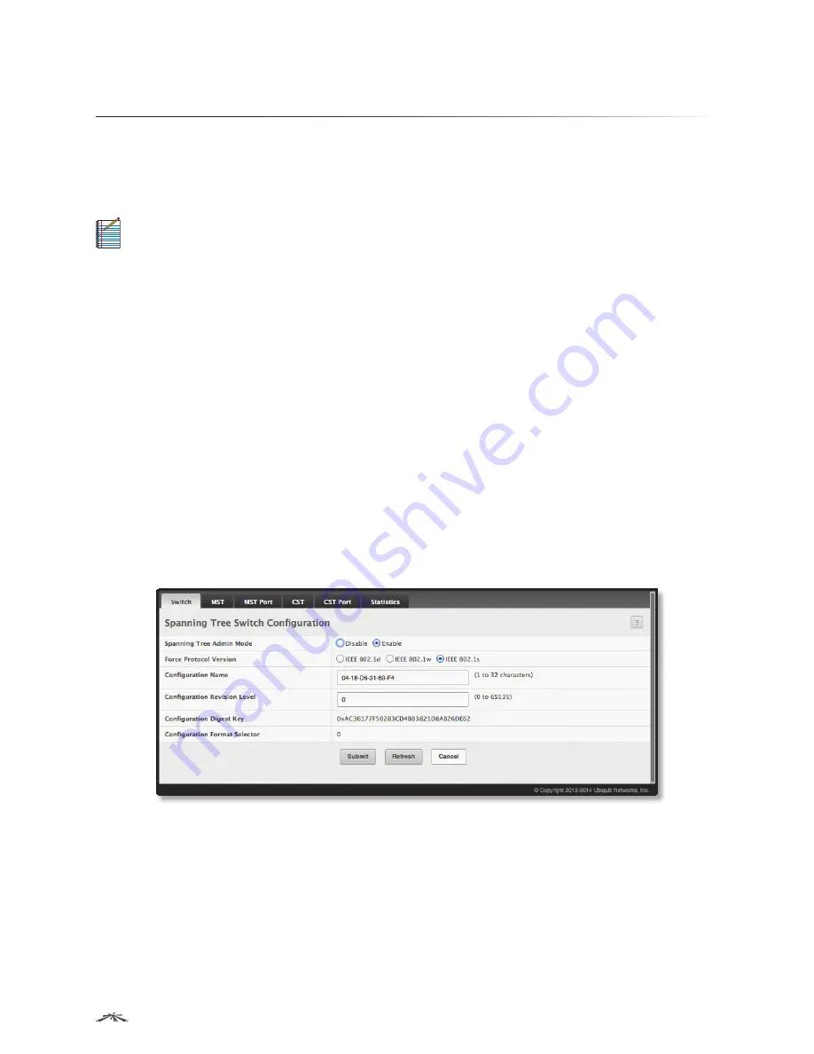
2. Enable MSTP (IEEE 802.1s) on the switch and change the configuration name.
a. Changing the configuration name allows all the bridges that want to be part of the same region to
join.
b. Go to the
Switching
>
Spanning Tree
>
Switch
page.
c. From the
Spanning Tree Admin Mode
field, select
Enable
.
d. In the
Configuration Name
field, enter
ubnt
.
e. Click
Submit
.
Spanning Tree Switch Configuration Page
3. Create two MST instances.
a. Go to the
Switching
>
Spanning Tree
>
MST
page.
b. From the
MST
page, click
Add
.
c. In the
MST ID
field, enter
10
.
d. Associate MST ID 10 with VLAN 10 and assign a bridge priority of
16384
.
e. Click
Submit
.


