


11
Getting Started
EdgeSwitch
™
Administration Guide
Ubiquiti Networks, Inc.
3. If this is your first login to the UI, read the license agreement. Then, click the
I agree to the terms of this
License Agreement
check box and click
Log In
.
4. After the system authenticates you, the
System Description
page is displayed.
EdgeSwitch UI Page Layout
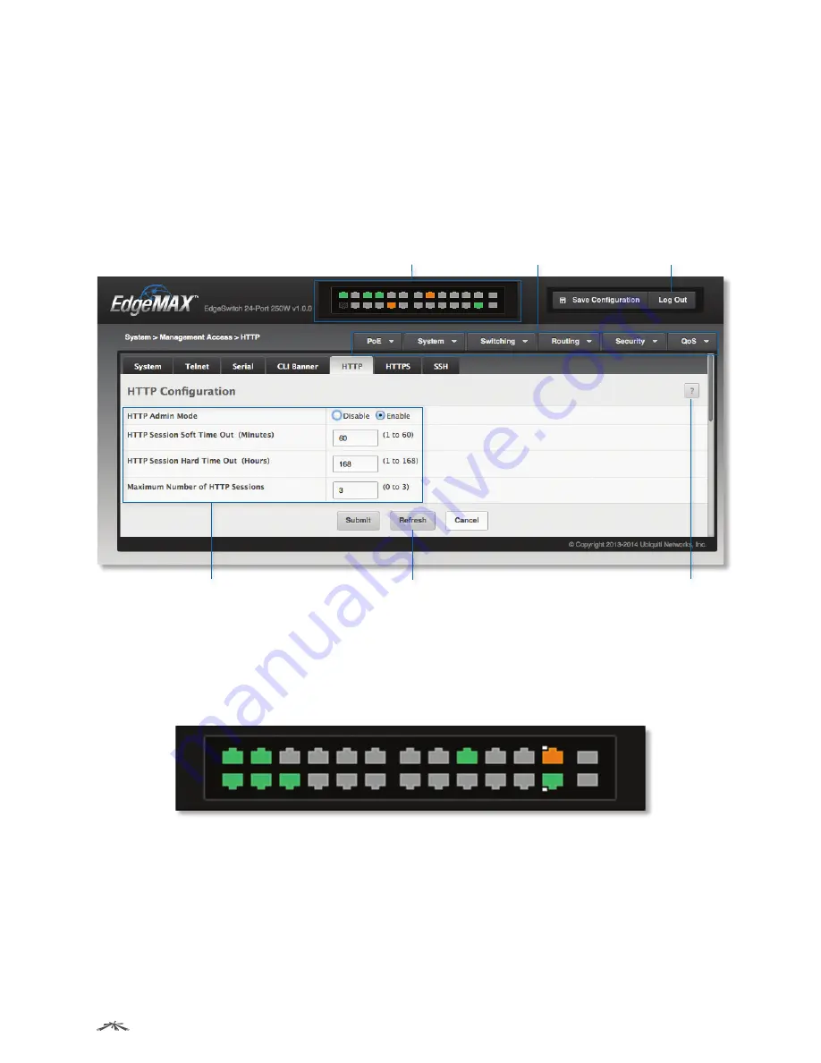
The following illustration shows the layout of a page in the EdgeSwitch UI. Each UI page contains three main
areas: the device view, the navigation menu, and the configuration and status fields. Each page also provides
buttons that let you perform operations on the displayed information, access a context-specific help page, or
log out of the system.
Device View
Logout Button
Navigation Menu
Configuration and Status Fields
Command Button
Help Page Access
EdgeSwitch UI Page Layout
Device View
The Device View shown in the illustration below is a Java® applet that displays the ports on the switch. This
graphic at the top of each UI page provides an alternate way to navigate to port-related configuration and
monitoring options. The graphic also provides information about device ports, current configuration and
status, table information, and feature components.
Example of Device View (24-Port Models)
In the Device View, colors indicate status information:
• Gray indicates that the port link is down.
• Amber indicates that the port link is up at 100 Mbps.
• Green indicates that the port link is up at 1 Gbps.
• A white dot indicates PoE output.


