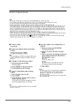
Playback
Recording
Editing
Function
setup
Others
Introduction
Others
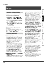
To protect recorded content
You can protect recorded content from unexpected
deletion.
Protection is provided for each title (original).
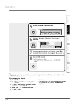
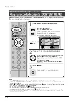
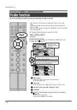
1) Perform steps 1 and 2 in “Playing recorded
contents (CONTENT MENU)” (
page 46) to
select a title.
2) Press the QUICK MENU button, and press the
/
buttons to select “Title information”. Then
press the ENTER button.
3) Press the QUICK MENU button, and press the
/
buttons to select “Lock” and then press
the ENTER button.
The mark
appears.
Notes
• To cancel protection, repeat this procedure. At step 3),
select “Unlock”.
• Disc initialization erases all titles on a disc even if they are
protected.
• Executing “All HDD titles delete” (
page 124) erases all
titles on the HDD even if they are protected.
Technical information
About recording time
The recording time of a typical VCR (Video Cassette
Recorder) is determined by the length of a video tape
and recording speed (SP, LP, etc.). Video tapes with
various recording times are available in the market.
On the other hand, the recording time of a DVD-RAM/
R/RW depends on the bit rate (Mbps: amount of data
transmitted per second), which can be varied in
MPEG2 (Moving Picture Experts Group2)
compression technology.
As an example, when you pour water into a bucket
from a faucet, the faster the water flows, the sooner
the bucket is filled with water. On the other hand, the
slower the water flows, the more slowly the bucket is
filled. The DVD-RAM/R/RW is, so to speak, such a
bucket, and the degree you turn the faucet is bit rate,
the time required to fill the bucket with water is the
recording time available for a disc. The higher you set
the bit rate (making much more water flow), the
sooner a disc is filled. Consequently, the recording
time becomes shorter. The lower you set the bit rate,
the longer time it takes to fill a disc.
About picture quality (XP, SP, LP, AT (Auto), MN
(Manual) mode)
The higher you set the bit rate, the more the volume of
information for the picture. The lower the bit rate, the
less the volume of picture information.
However a high bit rate does not always mean that the
picture quality is high. The difference between the 1.4
Mbps and 9.2 Mbps is obvious, but when comparing
similar bit rates, the difference may be insignificant.
Generally when you set the bit rate low for longer
recording time, the data volume shortage will result in
a lack of detail information. As a result, the picture
quality is decreased (more noticeable with dynamically
moving images). For example, square noises (block
noise) may occur in a scene with fast action or a
scene with light and shadows, such as a water
surface.
This recorder has several settings, for example 2 hour
recording at “SP” mode or 4 hour recording at “LP”
mode (both assume a blank 4.7 GB DVD-RAM). It is
recommended to consider the “SP” mode as a
standard mode and use the “LP” mode when you want
to record for long time regardless of the picture quality.
If you want to record for about 2 hours or are uncertain
which one to select, select the “AT” mode.
On a blank 4.7 GB DVD-RAM disc, the “AT” mode
automatically sets the appropriate bit rate
corresponded to the recording time from about 1 hour
to up to 2 and a half hours so that you can achieve the
best picture quality. If a part of a DVD-RAM disc has
already been recorded, the “AT” mode sets the bit rate
suitable for the remaining space on the disc. (The
picture quality is determined referring the remaining
space just before recording. When the remaining
space is scarce in the disc, the picture quality may
decrease from what you set beforehand or the
recording may stop halfway.) “AT” mode is available
also on DVD-R/RW recordings.
When you want to record a music program or
animation with high picture quality, it is recommended
that you select the “MN” mode. If you select more than
6 Mbps, you can usually record with considerably
higher picture quality. However the higher you set the
bit rate, the shorter the recording time.
D /M1,
D /M2
Sound recording format onto DVD-RAM discs. When
recording, sounds are converted into digital signals
and compressed. In playback, they are extracted to
the original sound. The standard differenciates
D /
M1 and
D /M2 in data volume to use.
D /M1
and
D /M2 are applied the digital recording
technology for consumer products of Dolby
Laboratories. Dolby Digital 192 kbps is set for
D /
M1 and Dolby Digital 384 kbps for
D /M2.
L-PCM (Linear PCM)
Sound recording format, like Dolby Digital. However,
sounds are converted into digital signals and recorded
as they are without compression. This process
requires more data than Dolby Digital.
Operating Instructions
12-30
Содержание RD-XS24SB
Страница 10: ...Product Specification 2 4 MEMO ...
Страница 12: ...3 2 Software Update MEMO ...
Страница 19: ...Disassembly and Reaasembly 4 7 4 2 PCB Location Fig 4 7 PCB Location S M P S PCB JACK PCB MAIN PCB ...
Страница 20: ...4 8 Disassembly and Reaasembly MEMO ...
Страница 34: ...Troubleshooting 5 14 MEMO ...
Страница 35: ...6 1 6 Exploded View and Parts List 6 1 Cabinet Assembly Page 6 2 ...
Страница 38: ...Exploded Views and Parts List 6 4 MEMO ...
Страница 50: ...Electrical Parts List 7 12 MEMO ...
Страница 160: ...Operating Instructions 12 110 MEMO ...
Страница 173: ...1 1 SHIBAURA 1 CHOME MINATO KU TOKYO 105 8001 JAPAN ...
Страница 177: ...Block Diagrams 8 3 8 2 Digital Block Diagram ...
Страница 180: ...Block Diagrams 8 6 8 5 AIC01 MSP3417 Block Diagram ...
Страница 181: ...Block Diagrams 8 7 8 6 AIC02 AIC07 MC14052 Block Diagram ...
Страница 182: ...Block Diagrams 8 8 8 7 AIC03 AK5357 Block Diagram ...
Страница 183: ...Block Diagrams 8 9 8 8 AIC04 PCM1753 Block Diagram ...
Страница 184: ...Block Diagrams 8 10 8 9 KIC01 PT6961 Block Diagram ...
Страница 185: ...Block Diagrams 8 11 8 10 MIC01 78F4225 Block Diagram ...
Страница 187: ...Block Diagrams 8 13 8 12 SIC01 MM1647 Block Diagram ...
Страница 188: ...Block Diagrams 8 14 8 13 VIC01 74HC4051 Block Diagram ...
Страница 189: ...Block Diagrams 8 15 8 14 VIC05 MM1568 Block Diagram ...
Страница 190: ...Block Diagrams 8 16 MEMO ...
Страница 191: ...9 Wiring Diagram 9 1 ...
Страница 192: ...Wiring Diagram 9 2 MEMO ...
Страница 193: ...10 1 10 PCB Diagrams 10 1 S M P S PCB 10 2 Main PCB 10 3 Jack PCB 10 4 Key PCB 10 2 10 4 10 6 10 8 ...
Страница 194: ...PCB Diagrams 10 2 10 1 S M P S PCB COMPONENT SIDE ...
Страница 195: ...PCB Diagrams 10 3 CONDUCTOR SIDE ...
Страница 196: ...PCB Diagrams 10 4 10 2 Main PCB COMPONENT SIDE ...
Страница 198: ...PCB Diagrams 10 6 10 3 Jack PCB COMPONENT SIDE ...
Страница 199: ...PCB Diagrams 10 7 CONDUCTOR SIDE ...
Страница 200: ...PCB Diagrams 10 8 10 4 Key PCB COMPONENT SIDE CONDUCTOR SIDE ...
Страница 202: ...Schematic Diagrams 11 2 11 1 S M P S SMPS PCB ...
Страница 203: ...Schematic Diagrams 11 3 11 2 Main Main PCB ...
Страница 204: ...Schematic Diagrams 11 4 11 3 Audio Jack PCB ...
Страница 205: ...Schematic Diagrams 11 5 11 4 Video Jack PCB ...
Страница 206: ...Schematic Diagrams 11 6 11 5 AV switch Scart Jack PCB ...
Страница 207: ...Schematic Diagrams 11 7 11 6 Tuner Front in Connection Jack PCB ...
Страница 208: ...Schematic Diagrams 11 8 11 7 Micom Jack PCB ...
Страница 209: ...Schematic Diagrams 11 9 11 8 Key Key PCB ...
Страница 210: ...Schematic Diagrams 11 10 MEMO ...


