


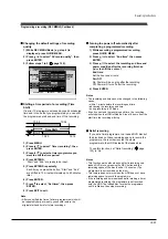


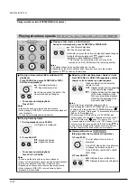


To stop recording
Press STOP.
To pause recording (to omit an unnecessary
portion)
During recording, press PAUSE.
To resume recording, press it again.
Note
• While recording onto a DVD disc, pressing PAUSE on the
recorder automatically creates a new chapter division at
that point.
To change a TV channel to be recorded
1) During recording, press PAUSE.
Recording pauses.
2) Press CHANNEL to change the channel.
3) Press PAUSE to resume recording.
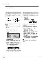
To view a TV programme while recording
another
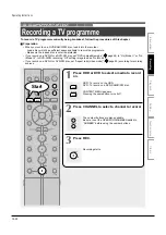
1) Start recording on this recorder.
2) Press TV/DVR.
3) Using the channel selector of the TV, select a
desired channel on the TV.
If you press the TV/DVR button again, you will go
back to the display that you are recording.
Note
• This function is available only when the TV is connected to
the AV1 (TV) socket.
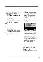
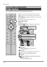
To set an end time of a recording which is in
progress
1) During recording, press QUICK MENU.
The Quick Menu appears.
2) Press / to select “End time” then press
ENTER .
3) Press / to select the recording end time and
power condition after the recording finishes.
( / to shift the cursor.)
End time:
Set the hour and minute.
Pwr Off:
On: Power will be on also after the recording.
Off: Power will turn off after the recording.
4) Press ENTER.
Notes
• By setting an end time, it is memorized as a programmed
one, and the
indicator in the front panel display
illuminates to indicate that the recorder holds a timer
program of recording.
• The programmed end time must be set for 5 minutes later
than the current time.
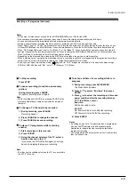
Recording a TV programme (Continued)
Notes
• The number of titles cannot exceed 99 for a DVD-RAM/RW/R disc or 396 for the HDD.
• One continuous recording cannot exceed in any case 8 hours. Recording automatically stops at 8 hours.
• You cannot start recording immediately before a programmed recording starts.
• During monaural sound recording, the same sound is recorded on both the left and right channels.
• When “Audio” is set to “L-PCM”, multi-channel sound is recorded as stereo sound. When playing this recorded sound, you
will hear NICAM Mode
I
and NICAM Mode
II
sounds simultaneously. Press the AUDIO button to select a desired sound.
• When “DVD compatible mode” is set to “On (Mode
I
)” or “On (Mode
II
)”, the unit records the same sounds on both the left
and right channels when receiving monaural sound. When receiving the NICAM Mode
I
/Mode
II
sound, the selected sound,
Mode
I
or Mode
II
, is recorded on both the left and right channels.
• Depending on the disc condition, pressing the REC button may take a longer time to start recording.
• When a starting time of a programmed recording comes, a recording in execution is stopped and the programmed recording
starts. If you do not want to stop the recording, cancel the timer program before it starts.
• Even if you set “Aspect ratio(video mode)” (
page 28) to “16:9”, images are recorded in 4:3 aspect ratio when using a
DVD-R or DVD-RW disc with “Pict.” set to “1.0” (Mbps) or “1.4” (Mbps).
Operating Instructions
12-25
Содержание RD-XS24SB
Страница 10: ...Product Specification 2 4 MEMO ...
Страница 12: ...3 2 Software Update MEMO ...
Страница 19: ...Disassembly and Reaasembly 4 7 4 2 PCB Location Fig 4 7 PCB Location S M P S PCB JACK PCB MAIN PCB ...
Страница 20: ...4 8 Disassembly and Reaasembly MEMO ...
Страница 34: ...Troubleshooting 5 14 MEMO ...
Страница 35: ...6 1 6 Exploded View and Parts List 6 1 Cabinet Assembly Page 6 2 ...
Страница 38: ...Exploded Views and Parts List 6 4 MEMO ...
Страница 50: ...Electrical Parts List 7 12 MEMO ...
Страница 160: ...Operating Instructions 12 110 MEMO ...
Страница 173: ...1 1 SHIBAURA 1 CHOME MINATO KU TOKYO 105 8001 JAPAN ...
Страница 177: ...Block Diagrams 8 3 8 2 Digital Block Diagram ...
Страница 180: ...Block Diagrams 8 6 8 5 AIC01 MSP3417 Block Diagram ...
Страница 181: ...Block Diagrams 8 7 8 6 AIC02 AIC07 MC14052 Block Diagram ...
Страница 182: ...Block Diagrams 8 8 8 7 AIC03 AK5357 Block Diagram ...
Страница 183: ...Block Diagrams 8 9 8 8 AIC04 PCM1753 Block Diagram ...
Страница 184: ...Block Diagrams 8 10 8 9 KIC01 PT6961 Block Diagram ...
Страница 185: ...Block Diagrams 8 11 8 10 MIC01 78F4225 Block Diagram ...
Страница 187: ...Block Diagrams 8 13 8 12 SIC01 MM1647 Block Diagram ...
Страница 188: ...Block Diagrams 8 14 8 13 VIC01 74HC4051 Block Diagram ...
Страница 189: ...Block Diagrams 8 15 8 14 VIC05 MM1568 Block Diagram ...
Страница 190: ...Block Diagrams 8 16 MEMO ...
Страница 191: ...9 Wiring Diagram 9 1 ...
Страница 192: ...Wiring Diagram 9 2 MEMO ...
Страница 193: ...10 1 10 PCB Diagrams 10 1 S M P S PCB 10 2 Main PCB 10 3 Jack PCB 10 4 Key PCB 10 2 10 4 10 6 10 8 ...
Страница 194: ...PCB Diagrams 10 2 10 1 S M P S PCB COMPONENT SIDE ...
Страница 195: ...PCB Diagrams 10 3 CONDUCTOR SIDE ...
Страница 196: ...PCB Diagrams 10 4 10 2 Main PCB COMPONENT SIDE ...
Страница 198: ...PCB Diagrams 10 6 10 3 Jack PCB COMPONENT SIDE ...
Страница 199: ...PCB Diagrams 10 7 CONDUCTOR SIDE ...
Страница 200: ...PCB Diagrams 10 8 10 4 Key PCB COMPONENT SIDE CONDUCTOR SIDE ...
Страница 202: ...Schematic Diagrams 11 2 11 1 S M P S SMPS PCB ...
Страница 203: ...Schematic Diagrams 11 3 11 2 Main Main PCB ...
Страница 204: ...Schematic Diagrams 11 4 11 3 Audio Jack PCB ...
Страница 205: ...Schematic Diagrams 11 5 11 4 Video Jack PCB ...
Страница 206: ...Schematic Diagrams 11 6 11 5 AV switch Scart Jack PCB ...
Страница 207: ...Schematic Diagrams 11 7 11 6 Tuner Front in Connection Jack PCB ...
Страница 208: ...Schematic Diagrams 11 8 11 7 Micom Jack PCB ...
Страница 209: ...Schematic Diagrams 11 9 11 8 Key Key PCB ...
Страница 210: ...Schematic Diagrams 11 10 MEMO ...


