Operating Instructions
12-104
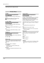
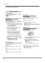
Customizing the function settings (Continued)
Display settings
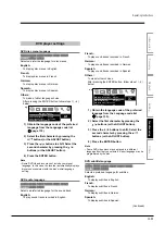
TV Shape
HDD
DVD-RAM
DVD-RW
(VR)
DVD-RW
(Video)
DVD-R
(VR)
DVD-VIDEO
VCD
CD
DVD-R
(Video)
Selects a picture size according to the aspect ratio of
your TV.
For details on this setting, see “TV shape setting”
(
page 36, “INSTALLATION GUIDE”).
On screen display
HDD
DVD-RAM
DVD-RW
(VR)
DVD-RW
(Video)
DVD-R
(VR)
DVD-VIDEO
VCD
CD
DVD-R
(Video)
Turns on or deactivate the operational status display
(e.g.,
) on the TV screen.
Off:
Deactivates the operational status display (e.g.,
) on
the TV screen.
On:
Activates the operational status display (e.g.,
) on
the TV screen.
Transparency
HDD
DVD-RAM
DVD-RW
(VR)
DVD-RW
(Video)
DVD-R
(VR)
DVD-VIDEO
VCD
CD
DVD-R
(Video)
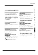
Selects the transparency of the GUI and its relationship
to the background image.
0% : 25% : 50%
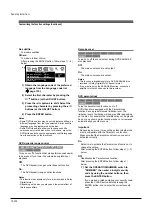
Startup screen
Turns on or off the start-up screen setting that makes the
background picture appear automatically when turning
on the power.
Off:
The startup screen is not displayed.
On: Animation
The startup screen appears automatically when
turning on the power.
On: menu
The Menu screen appears automatically when turning
on the power.
Screen protector
HDD
DVD-RAM
DVD-RW
(VR)
DVD-RW
(Video)
DVD-R
(VR)
DVD-VIDEO
VCD
CD
DVD-R
(Video)
Turns the screen saver on or off.
To reduce TV screen damage (image burn), this function
disengages the pause mode of a playback image. The
display returns to the normal TV screen when the
recorder remains idle for more than 15 minutes. In time
slip mode, the playback pause is released.
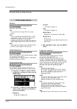
If this function is set to “On”, the recorder, if freezes, may
return to the normal by leaving it for about 15 minutes or
longer.
Off:
Deactivates the screen protector function.
On:
Activates the screen protector function.
Note
• Toshiba does not guarantee that this function protects the
TV screen by all means.
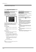
Background
Selects a screen colour when receiving no video signals
such as selecting a non-broadcasting channel.
Off:
No colour.
Black:
Black is displayed.
Blue:
Blue is displayed.
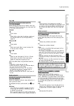
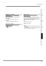
Important
• Depending on signal reception, the Background setting
may be cleared. To prevent this, set this function to
“Off”.
Содержание RD-XS24SB
Страница 10: ...Product Specification 2 4 MEMO ...
Страница 12: ...3 2 Software Update MEMO ...
Страница 19: ...Disassembly and Reaasembly 4 7 4 2 PCB Location Fig 4 7 PCB Location S M P S PCB JACK PCB MAIN PCB ...
Страница 20: ...4 8 Disassembly and Reaasembly MEMO ...
Страница 34: ...Troubleshooting 5 14 MEMO ...
Страница 35: ...6 1 6 Exploded View and Parts List 6 1 Cabinet Assembly Page 6 2 ...
Страница 38: ...Exploded Views and Parts List 6 4 MEMO ...
Страница 50: ...Electrical Parts List 7 12 MEMO ...
Страница 160: ...Operating Instructions 12 110 MEMO ...
Страница 173: ...1 1 SHIBAURA 1 CHOME MINATO KU TOKYO 105 8001 JAPAN ...
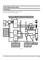
Страница 177: ...Block Diagrams 8 3 8 2 Digital Block Diagram ...
Страница 180: ...Block Diagrams 8 6 8 5 AIC01 MSP3417 Block Diagram ...
Страница 181: ...Block Diagrams 8 7 8 6 AIC02 AIC07 MC14052 Block Diagram ...
Страница 182: ...Block Diagrams 8 8 8 7 AIC03 AK5357 Block Diagram ...
Страница 183: ...Block Diagrams 8 9 8 8 AIC04 PCM1753 Block Diagram ...
Страница 184: ...Block Diagrams 8 10 8 9 KIC01 PT6961 Block Diagram ...
Страница 185: ...Block Diagrams 8 11 8 10 MIC01 78F4225 Block Diagram ...
Страница 187: ...Block Diagrams 8 13 8 12 SIC01 MM1647 Block Diagram ...
Страница 188: ...Block Diagrams 8 14 8 13 VIC01 74HC4051 Block Diagram ...
Страница 189: ...Block Diagrams 8 15 8 14 VIC05 MM1568 Block Diagram ...
Страница 190: ...Block Diagrams 8 16 MEMO ...
Страница 191: ...9 Wiring Diagram 9 1 ...
Страница 192: ...Wiring Diagram 9 2 MEMO ...
Страница 193: ...10 1 10 PCB Diagrams 10 1 S M P S PCB 10 2 Main PCB 10 3 Jack PCB 10 4 Key PCB 10 2 10 4 10 6 10 8 ...
Страница 194: ...PCB Diagrams 10 2 10 1 S M P S PCB COMPONENT SIDE ...
Страница 195: ...PCB Diagrams 10 3 CONDUCTOR SIDE ...
Страница 196: ...PCB Diagrams 10 4 10 2 Main PCB COMPONENT SIDE ...
Страница 198: ...PCB Diagrams 10 6 10 3 Jack PCB COMPONENT SIDE ...
Страница 199: ...PCB Diagrams 10 7 CONDUCTOR SIDE ...
Страница 200: ...PCB Diagrams 10 8 10 4 Key PCB COMPONENT SIDE CONDUCTOR SIDE ...
Страница 202: ...Schematic Diagrams 11 2 11 1 S M P S SMPS PCB ...
Страница 203: ...Schematic Diagrams 11 3 11 2 Main Main PCB ...
Страница 204: ...Schematic Diagrams 11 4 11 3 Audio Jack PCB ...
Страница 205: ...Schematic Diagrams 11 5 11 4 Video Jack PCB ...
Страница 206: ...Schematic Diagrams 11 6 11 5 AV switch Scart Jack PCB ...
Страница 207: ...Schematic Diagrams 11 7 11 6 Tuner Front in Connection Jack PCB ...
Страница 208: ...Schematic Diagrams 11 8 11 7 Micom Jack PCB ...
Страница 209: ...Schematic Diagrams 11 9 11 8 Key Key PCB ...
Страница 210: ...Schematic Diagrams 11 10 MEMO ...


