


Operating Instructions
12-69
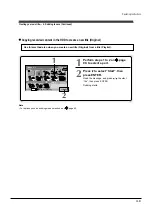
7
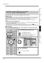
Press
/ to select a point where you want to
insert the item, then press ENTER.
If there are no parts in the lower area, leave the cursor
to the left and press the ENTER button.
The selected part is inserted at the location of the
cursor.
8
Repeat steps 5 to 7 to insert items.
To cancel the selection, see “Cancelling selection of a part”
(
page 105).
9
When all items have been inserted, press
RETURN.
The recorder displays a message, and starts saving the
Playlist.
When complete, the “EDIT MENU Main Menu” returns.
If the part first chosen is in a folder, the playlist will be
created in this folder.
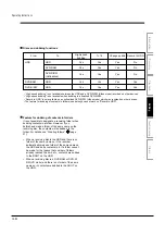
Notes
• If you delete titles and chapters (Original), the corresponding titles and chapters (Playlist) are also deleted. Contrarily, if you
delete titles and chapters (Playlist), the corresponding titles and chapters (Original) are not deleted.
• Playback may pause if a gap between the content is played.
• There may be a small difference between the chapter boundary and the actual playback picture.
• A title or chapter which is being edited cannot be selected as an item.
• You cannot add a title of still pictures, or a title or a chapter which contains both still and moving pictures, to a playlist.
• By copying (dubbing) a Playlist, a title (Original) of the same contents is created.
• You cannot program a Playlist of contents recorded on a DVD-R/RW disc (Video mode). To make a Playlist using contents of
DVD-RW discs (Video mode), copy them to the HDD beforehand.
• Down arrow on the thumbnails means: Orange: This title already selected. Green trimmed: Some chapters in this title already
selected. Green: This chapter already selected.
• A black thumbnail with “Recording” means that the title is being recorded or its recording will start within 15 seconds. This
thumbnail cannot start playback.
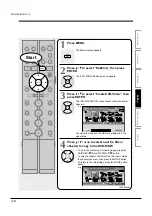
ENTER
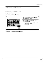
Creating your own title — 3: Collecting necessary scenes (Continued)
RETURN
1
2
3
4
5
6
7
8
9
+10
0
TV
DVD
INPUT SELECT
CHANNEL
MODE
RETURN
SLOW/REV
FWD/SLOW
PLAY
STOP
PAUSE
REC
SKIP REV
SKIP FWD
–ADJUST
TV/DVR
DELETE
CLEAR
EXIT
QUICK MENU
OPERATION
INSTANT
SKIP
INSTANT
REPLAY
NUMBER
HDD
DVD
TOP MENU
MENU
MENU
TIMESLIP
CHANNEL
VOLUME
INPUT SELECT
OPEN/CLOSE
CHP DIVIDE ANGLE
SUBTITLE
AUDIO
REC MODE ZOOM
SEARCH DISPLAY
ENTER
HDD (VR)
HDD :
Playlist Editing
Original
Play List
Source: (VR)Title
Object: Title
Start
Title:
Entire Time:
00:13:45
2005/11/07 10:30
E D I T
MENU
11
001
e.g.
Содержание RD-XS24SB
Страница 10: ...Product Specification 2 4 MEMO ...
Страница 12: ...3 2 Software Update MEMO ...
Страница 19: ...Disassembly and Reaasembly 4 7 4 2 PCB Location Fig 4 7 PCB Location S M P S PCB JACK PCB MAIN PCB ...
Страница 20: ...4 8 Disassembly and Reaasembly MEMO ...
Страница 34: ...Troubleshooting 5 14 MEMO ...
Страница 35: ...6 1 6 Exploded View and Parts List 6 1 Cabinet Assembly Page 6 2 ...
Страница 38: ...Exploded Views and Parts List 6 4 MEMO ...
Страница 50: ...Electrical Parts List 7 12 MEMO ...
Страница 160: ...Operating Instructions 12 110 MEMO ...
Страница 173: ...1 1 SHIBAURA 1 CHOME MINATO KU TOKYO 105 8001 JAPAN ...
Страница 177: ...Block Diagrams 8 3 8 2 Digital Block Diagram ...
Страница 180: ...Block Diagrams 8 6 8 5 AIC01 MSP3417 Block Diagram ...
Страница 181: ...Block Diagrams 8 7 8 6 AIC02 AIC07 MC14052 Block Diagram ...
Страница 182: ...Block Diagrams 8 8 8 7 AIC03 AK5357 Block Diagram ...
Страница 183: ...Block Diagrams 8 9 8 8 AIC04 PCM1753 Block Diagram ...
Страница 184: ...Block Diagrams 8 10 8 9 KIC01 PT6961 Block Diagram ...
Страница 185: ...Block Diagrams 8 11 8 10 MIC01 78F4225 Block Diagram ...
Страница 187: ...Block Diagrams 8 13 8 12 SIC01 MM1647 Block Diagram ...
Страница 188: ...Block Diagrams 8 14 8 13 VIC01 74HC4051 Block Diagram ...
Страница 189: ...Block Diagrams 8 15 8 14 VIC05 MM1568 Block Diagram ...
Страница 190: ...Block Diagrams 8 16 MEMO ...
Страница 191: ...9 Wiring Diagram 9 1 ...
Страница 192: ...Wiring Diagram 9 2 MEMO ...
Страница 193: ...10 1 10 PCB Diagrams 10 1 S M P S PCB 10 2 Main PCB 10 3 Jack PCB 10 4 Key PCB 10 2 10 4 10 6 10 8 ...
Страница 194: ...PCB Diagrams 10 2 10 1 S M P S PCB COMPONENT SIDE ...
Страница 195: ...PCB Diagrams 10 3 CONDUCTOR SIDE ...
Страница 196: ...PCB Diagrams 10 4 10 2 Main PCB COMPONENT SIDE ...
Страница 198: ...PCB Diagrams 10 6 10 3 Jack PCB COMPONENT SIDE ...
Страница 199: ...PCB Diagrams 10 7 CONDUCTOR SIDE ...
Страница 200: ...PCB Diagrams 10 8 10 4 Key PCB COMPONENT SIDE CONDUCTOR SIDE ...
Страница 202: ...Schematic Diagrams 11 2 11 1 S M P S SMPS PCB ...
Страница 203: ...Schematic Diagrams 11 3 11 2 Main Main PCB ...
Страница 204: ...Schematic Diagrams 11 4 11 3 Audio Jack PCB ...
Страница 205: ...Schematic Diagrams 11 5 11 4 Video Jack PCB ...
Страница 206: ...Schematic Diagrams 11 6 11 5 AV switch Scart Jack PCB ...
Страница 207: ...Schematic Diagrams 11 7 11 6 Tuner Front in Connection Jack PCB ...
Страница 208: ...Schematic Diagrams 11 8 11 7 Micom Jack PCB ...
Страница 209: ...Schematic Diagrams 11 9 11 8 Key Key PCB ...
Страница 210: ...Schematic Diagrams 11 10 MEMO ...


