


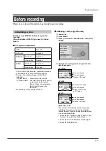


Setting for recording on a DVD-R/RW disc in Video mode
Video mode recording enables playback of your favorite contents on other devices such as DVD players.
Finish this setting beforehand if you make a Video mode recording, that is;
- when you record on a DVD-R/RW (Video mode).
- when you record contents which will be copied from the HDD to a DVD-R/RW (Video mode).
Items to set up
When recording in Video mode, there are some
restrictions by DVD-Video standard.
Therefore, it is necessary to set up these items below.
Set up the items in advance before copying contents
from the HDD to a DVD-R/RW (Video mode) disc.
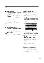
DVD compatible mode
Only the left channel sound and the right channel
sound are available for recording in Video mode
under DVD-R/RW standard.
Off:
This is not for recording on a DVD-R/
RW disc.Depending on Picture/Audio
settings, making DVD Video may not
be possible. (When recording directly
on a DVD-R/RW disc of Video mode,
the recording proceeds with “On
(Mode
I
)” on even though “Off” is
set.)
On (Mode
I
): In multichannel broadcasting, only
the left channel sound is recorded.
On (Mode
II
): In multichannel broadcasting, only
the right channel sound is recorded.
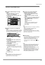
Aspect ratio (Video mode)
“4:3” and “16:9” cannot be mixed in one title.
Therefore, set the aspect ratio before recording.
4:3:
Set the aspect ratio to 4:3
16:9: Set the aspect ratio to 16:9
DVD-Video: CHP create
This is the setting to divide a title into some
chapters. It is convenient to skip scenes.
Off:
Chapter dividing is not available.
5 min, 10 min, 15 min, 20 min:
Select an interval for chapter dividing.
Note
• When the number of chapters reaches a limit, chapters
are not divided anymore. The limit number of chapters is
dependent on conditions of a DVD-R/RW disc.
Note
• This setting is not effective in dubbing.
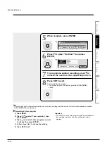
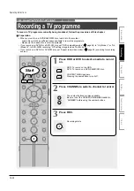
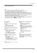
1
Press SETUP during stop.
SETUP menu appears.
2
Select “DVD recorder operation”
and press ENTER.
3
Select “Video mode rec.
setting” and press ENTER.
4
Press / to select an item
then press / to change the
setting, and finally press
ENTER.
How to set up
e.g.
e.g.
SETUP
ENTER
ENTER
ENTER
DVD-RW rec. mode setting
Video mode rec. setting
Picture record mode
Video mode
On
AV record quality
DVD recorder operation
Relief recording
Picture record mode
AV record quality
On
DVD recorder operation
Relief recording
DVD-RW rec. mode setting
Video mode
Video mode rec. setting
Initializing a disc (Continued)
Operating Instructions
12-15
Содержание RD-XS24SB
Страница 10: ...Product Specification 2 4 MEMO ...
Страница 12: ...3 2 Software Update MEMO ...
Страница 19: ...Disassembly and Reaasembly 4 7 4 2 PCB Location Fig 4 7 PCB Location S M P S PCB JACK PCB MAIN PCB ...
Страница 20: ...4 8 Disassembly and Reaasembly MEMO ...
Страница 34: ...Troubleshooting 5 14 MEMO ...
Страница 35: ...6 1 6 Exploded View and Parts List 6 1 Cabinet Assembly Page 6 2 ...
Страница 38: ...Exploded Views and Parts List 6 4 MEMO ...
Страница 50: ...Electrical Parts List 7 12 MEMO ...
Страница 160: ...Operating Instructions 12 110 MEMO ...
Страница 173: ...1 1 SHIBAURA 1 CHOME MINATO KU TOKYO 105 8001 JAPAN ...
Страница 177: ...Block Diagrams 8 3 8 2 Digital Block Diagram ...
Страница 180: ...Block Diagrams 8 6 8 5 AIC01 MSP3417 Block Diagram ...
Страница 181: ...Block Diagrams 8 7 8 6 AIC02 AIC07 MC14052 Block Diagram ...
Страница 182: ...Block Diagrams 8 8 8 7 AIC03 AK5357 Block Diagram ...
Страница 183: ...Block Diagrams 8 9 8 8 AIC04 PCM1753 Block Diagram ...
Страница 184: ...Block Diagrams 8 10 8 9 KIC01 PT6961 Block Diagram ...
Страница 185: ...Block Diagrams 8 11 8 10 MIC01 78F4225 Block Diagram ...
Страница 187: ...Block Diagrams 8 13 8 12 SIC01 MM1647 Block Diagram ...
Страница 188: ...Block Diagrams 8 14 8 13 VIC01 74HC4051 Block Diagram ...
Страница 189: ...Block Diagrams 8 15 8 14 VIC05 MM1568 Block Diagram ...
Страница 190: ...Block Diagrams 8 16 MEMO ...
Страница 191: ...9 Wiring Diagram 9 1 ...
Страница 192: ...Wiring Diagram 9 2 MEMO ...
Страница 193: ...10 1 10 PCB Diagrams 10 1 S M P S PCB 10 2 Main PCB 10 3 Jack PCB 10 4 Key PCB 10 2 10 4 10 6 10 8 ...
Страница 194: ...PCB Diagrams 10 2 10 1 S M P S PCB COMPONENT SIDE ...
Страница 195: ...PCB Diagrams 10 3 CONDUCTOR SIDE ...
Страница 196: ...PCB Diagrams 10 4 10 2 Main PCB COMPONENT SIDE ...
Страница 198: ...PCB Diagrams 10 6 10 3 Jack PCB COMPONENT SIDE ...
Страница 199: ...PCB Diagrams 10 7 CONDUCTOR SIDE ...
Страница 200: ...PCB Diagrams 10 8 10 4 Key PCB COMPONENT SIDE CONDUCTOR SIDE ...
Страница 202: ...Schematic Diagrams 11 2 11 1 S M P S SMPS PCB ...
Страница 203: ...Schematic Diagrams 11 3 11 2 Main Main PCB ...
Страница 204: ...Schematic Diagrams 11 4 11 3 Audio Jack PCB ...
Страница 205: ...Schematic Diagrams 11 5 11 4 Video Jack PCB ...
Страница 206: ...Schematic Diagrams 11 6 11 5 AV switch Scart Jack PCB ...
Страница 207: ...Schematic Diagrams 11 7 11 6 Tuner Front in Connection Jack PCB ...
Страница 208: ...Schematic Diagrams 11 8 11 7 Micom Jack PCB ...
Страница 209: ...Schematic Diagrams 11 9 11 8 Key Key PCB ...
Страница 210: ...Schematic Diagrams 11 10 MEMO ...


