


3-143
<Measurement of oil volume>
*
Measure oil volume extracted from the compressor, and determine whether to add oil or not.
Recovered oil volume (cc) –2000 (cc) = Oil volume to be added (cc) (If the calculated volume is minus
value, addition is unnecessary.)
<Charging of oil>
Insert the hose up to the end of suction pipe mounting part of the compressor to be installed, and add the
necessary amount of oil using a funnel, etc.
<Installation>
• Install the compressor in the reverse order of removing of compressor.
NOTE :
After installation, open fully the valve at bottom side of the compressor, using hexagonal wrench.
<Vacuuming>
• Connect the vacuum pump to the check joint of the discharge and suction pipes, and operate the vacuum pump.
• Perform vacuuming until the vacuum low-pressure gauge indicates 1 (mmHg).
<Charging of refrigerant>
Add refrigerant of the same volume to the recovered refrigerant into the check joint of the suction pipe.
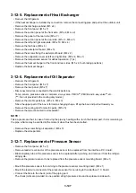
[In case of removal of the compressor from the rear side]
1. Outdoor unit (Inverter and fixed-speed units)
080, 100 type
<Removing of parts>
• Remove the front panel. (M5 x 7)
• Disconnect all wires connected to the electric parts box.
Temp. sensor, pressure sensor, complete, 2-way valve,
PMV A
*
, PMV B and 4-way valve
*
, etc.
(
*
: It is not provided in the cooling only model.)
• Remove the electric parts box. (M5 x 4, M4 x 3)
• Remove the cooling duct for the electric parts. (M5 x 5)
• Remove the crank case heater.
(Only for constant-speed unit)
• Remove the sound-proof mat.
• Remove the terminal cover of the compressor, and
remove all wires.
• Close the valve located under the compressor fully
using a hexadecimal wrench.
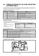
<Extraction of oil from compressor>
• Cut the case bypass located at the bottom of the
compressor by height same as that of the suction pipe.
• Connect hose to the cut case bypass, and insert the
opposite side of the hose in the container which oil is entered.
7.5
l
or more oil may flow through the hose, so use a
container with capacity of 8
l
or more.
• Apply nitrogen gas with approx. 0.02MPa from service valve at gas side to extract oil.
(Extract oil completely.) (Be sure to spurt of oil when gas is applied exceedingly.)
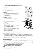
<Removing of compressor>
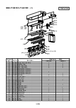
• Remove two discharge pipes, suction pipe, upper oil return piping, oil tank piping, and case bypass piping.
(Same as case of pulling out from the front side)
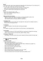
Accumlator
Compressor
Oil tank
Oil
separator
Содержание MMC-P0151H
Страница 198: ...3 195 108 109 101 102 133 106 131 105 135 128 104 103 111 110 123 116 132 119 120 121 MMY MP06018 ...
Страница 206: ...3 203 108 109 101 102 133 106 131 105 135 128 104 103 111 110 123 116 132 119 120 121 MMY MP0601H8 ...
Страница 214: ...3 211 108 109 101 102 133 106 131 105 135 128 104 103 111 110 123 116 132 119 120 121 MMY MP0601H7 ...
Страница 216: ...TOSHIBA CARRIER CORPORATION 336 TADEHARA FUJI SHI SHIZUOKA KEN 416 8521 JAPAN ...


