


3-136
3-10. REFRIGERANT RECOVERY METHOD WHEN
REPLACING THE COMPRESSOR
3-10-1. Refrigerant Recovery Method in the Failed Outdoor Unit
A reclaim function is provided to this A/C. When multiple outdoor units are connected in the system, the refriger-
ant can be recovered from the outdoor unit to be repaired by performing the reclaim operation in a normal
outdoor unit.
*
NOTE 1 : In reclaim function, the refrigerant recovery ratio changes according to the outside temp., etc.
After reclaim operation, recover the remained gas using a recovery device, etc., and be sure to
measure the recovered refrigerant amount. (When operating the reclaim heating the accumulator of
the outdoor unit to be repaired, the recovery ratio of refrigerant increases.)
* NOTE 2 : After this is complate, the system cannot be operated until the failed outdoor unit has been com-
pletely repaired. (Continuous operation is unavailable because of refrigerant over-charge operation.)
* NOTE 3 : While FULL CLOSE alarm (valve cannot be opened) of PMV A
*
and PMV B is output, the reclaim
work is not performed because refrigerant in the liquid tank cannot be recovered. In this case,
recover all refrigerant in the system using a recovery device, etc.
(
*
: It is not provided in the cooling only model.)
<Work procedure (A)>
For the positions of “Liquid pipe service valve”, “Gas pipe service valve”, and “Balancing pipe service valve”
described in the explanation of the work procedure, refer to the layout diagram in P.150.
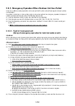
[In case that backup operation is not executed for fault of outdoor unit.]
A-1) Turn on the power supply of all the outdoor units, and keep the system in stop status (Indoor unit stop).
If insulation of the compressor is insufficient, remove lead wire of the compressor before turning on the
power supply.
A-2) For the failed outdoor unit, execute the following operations.
1) Close fully the liquid service valve onlye.
(Keep the service valves of gas pipe and balancing pipe opened fully.)
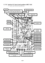
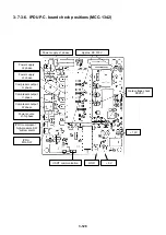
2) Set the rotary switches on the interface P.C. board to the following numbers.
• SW03 [No.1]/SW02 [No.11]/SW01 [No.2]
• 7 segment display : [r .][d ][ ][ ]
3) Keep pushing the push-switch SW04 on the interface P.C. board for 5 seconds or more.
Start the following operations.
*
When interrupting the work, turn off the power supply of all the outdoor units or push the push-switch
SW05 on the interface P.C. board.
a. 7 segment display : [r .][d ][1 ][1 ]
b. Operate the outdoor fan.
c. PMV A
*
, PMV B open. (
*
: It is not provided in the cooling only model.)
d. Solenoid valves SV3A, SV3B, and SV3C are turned on.
e. Other outdoor units start automatic operation in trial cooling mode.
(It may take a little time to activate the compressor.)
4) Push the push-switch SW04 on the interface P.C. board for approx. 2 seconds.
The present refrigerant pressure data (MPa) is displayed.
• 7 segment display : [H ][
*
.][
*
][
*
] (
*
: Value of Pd pressure sensor)
*
Every push of the push-switch SW04 the display changes.
<Initial display>
<Pd pressure>
<Ps pressure>
[r .][d ][1 ][1 ]
→
[H ][
*
.][
*
][
*
]
→
[L ][
*
.][
*
][
*
]
↑
Содержание MMC-P0151H
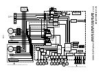
Страница 198: ...3 195 108 109 101 102 133 106 131 105 135 128 104 103 111 110 123 116 132 119 120 121 MMY MP06018 ...
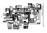
Страница 206: ...3 203 108 109 101 102 133 106 131 105 135 128 104 103 111 110 123 116 132 119 120 121 MMY MP0601H8 ...
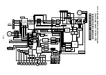
Страница 214: ...3 211 108 109 101 102 133 106 131 105 135 128 104 103 111 110 123 116 132 119 120 121 MMY MP0601H7 ...
Страница 216: ...TOSHIBA CARRIER CORPORATION 336 TADEHARA FUJI SHI SHIZUOKA KEN 416 8521 JAPAN ...


