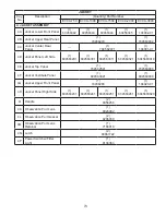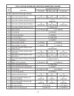
87
R
em
ot
e
Sys
tem
T
em
pe
rat
ure
(10k
oh
m
T
her
m
is
ter
, 5
Vdc)
O
ut
si
de
A
ir T
em
perat
ure
(10k
oh
m
T
her
m
is
ter
, 5
Vdc)
D
om
es
tic H
ot
W
at
er
Priorit
y
Loca
l /
R
em
ot
e
R
em
ot
e O
n /
O
ff (En
able)
S
par
e I
npu
t (
Pro
gra
m
m
able)
12 V
dc
C
om
m
on
R
em
ot
e
Fi
ring
R
at
e or
S
et
poin
t I
npu
t (
0-1
0 V
dc)
(Se
e N
ot
e)
M
ixi
ng Val
ve O
ut
put
(4-
20
m
Adc)
Lock
out
In
dic
at
or
S
par
e O
ut
put
St
art
/St
op
B
oil
er
Pum
p S
tar
t/St
op
S
yst
em
Pum
p S
tar
t/St
op
S
pa
re
O
ut
pu
t (P
ro
gram
m
able)
12V
dc
C
om
m
on
CA
OO
A
lter
na
te
C
on
ne
ct
ion F
or
O
ut
si
de
A
ir T
em
pe
rat
ure and
R
em
ot
e
Sys
tem
T
em
pe
rat
ure
(10k
oh
m
T
her
m
is
ter
, 5
Vdc)
C
al
l F
or H
eat
Out
put
Low
W
at
er
C
ut
of
f Sw
itc
h I
nput
B
oil
er
O
ut
let
T
em
pe
rat
ure
(10k
oh
m
T
her
m
is
ter
, 5
Vd
c)
C
om
m
on
B
oi
le
r I
nle
t T
em
perat
ure
B
oi
le
r Pe
er
-T
o-
Peer
C
om
m
uni
cat
ion
N
et
w
ork
V-
V+
P-
P+
GP
WF
HL
P
ow
er
C
om
m
on
(-
24 Vac)
P
ow
er
S
up
pl
y
(+
24
Vac)
Fla
m
e S
af
eg
ua
rd Alarm
(24
V
ac)
Fue
l Va
lv
e En
ergized
(24
V
ac)
P
-, P
+
- F
iri
ng
R
at
e
D
em
and
(0-10 Vdc,
PWM
)
V
-, V
+
- F
iri
ng
R
at
e
D
em
and
(0-10 Vdc)
O
O
-
Bu
rn
er
O
n/
Of
f Sw
itch
W
F - Lo
w
W
at
er F
low
Sw
itch
G
P - G
as Pr
es
su
re
Sw
itch
H
L - O
per
at
in
g or
H
igh
Lim
it
C
A - Lo
w
C
om
bus
tion
A
ir
Flow
Ther
mal
S
ol
utions
B
oi
le
r Co
nt
ro
l
™
(T
SB
C
™
)
TE
RM
IN
AL
L
AY
OU
T GU
ID
E
RJ
-4
5
(8 pi
n)
O+
O-
O-
R+
R+
R-
R-
DP
O+
LR
RO
SI
C
C
C
SP
BP
VI
LO
C-
C+
MR
MS
SO
C
C
BC
BO
BI
CH
LC
C
PR
AL
CS
RJ
-1
1
(6 pi
n)
12 V
dc,
0.
5 A
m
ax
tot
al
for L
O
, V
I, BP,
S
P a
nd
SO
24 Vac
12 Vdc
Label 1011
75
-0
4
24 Vac
W
A
RNIN
G
:
A
ll
con
nec
tio
ns
hav
e d
iff
ere
nt
inp
ut
s an
d o
ut
put
s.
R
ef
er t
o c
onn
ect
ion
s o
n d
iag
ram
s f
or
ind
ivi
dua
l i
npu
ts/
out
put
s.
(T
erm
in
al
c
on
ne
ct
io
ns
a
s
vi
ew
ed
fro
m
front
of
boiler)
N
O
TE:
V
al
id
s
ig
na
l ra
ng
e
fo
r t
erm
in
al
s
C
+ a
nd
C
- is 1-9VD
C
.
S
ee
b
oi
le
r w
iri
ng
d
ia
gr
am
for det
ails.
Содержание EVCA SERIES
Страница 13: ...13 Figure 3 Typical Sidewall Pressurized Venting Optional Figure 2 Typical Sidewall Pressurized Venting ...
Страница 14: ...14 Figure 4 Typical Vertical Pressurized Venting ...
Страница 16: ...16 Figure 6 Vertical Air Intake Piping Figure 5 Horizontal Air Intake Piping ...
Страница 19: ...19 Figure 8 Schematic Boiler Piping ...
Страница 25: ...25 Figure 9a 208 230 480V 1PH 3PH 60HZ Supply Power Wiring Schematic ...
Страница 26: ...26 Figure 9b 120V 1PH 60HZ Supply Power Wiring Schematic ...
Страница 27: ...27 Figure 9c Control Wiring Schematic EVCA 750 2000 ...
Страница 29: ...29 Figure 9e Control Wiring Schematic EVCA 3000 ...
Страница 32: ...32 Figure 10 Modular System Horizontal Air Intake Piping ...
Страница 33: ...33 Figure 11 Modular System Vertical Air Intake Piping ...
Страница 34: ...34 Figure 12 Modular System Typical One Pipe Water Piping ...
Страница 35: ...35 Figure 13 Modular System Typical Primary Secondary Water Piping ...
Страница 36: ...36 Figure 14 Modular System Typical Primary Secondary without System Pump ...
Страница 37: ...37 Figure 15 Modular System Typical Reverse Return Water Piping ...
Страница 38: ...38 Figure 16 Modular System Reverse Return with System Pump Only ...
Страница 39: ...39 Figure 17 Modular System Typical Primary Secondary with Reverse Return ...
Страница 55: ...55 Figure 18 Cleaning Secondary Heat Exchanger 1 2 ...
Страница 56: ...56 This page intentionally left blank ...
Страница 58: ...58 Figure 19 Boiler Combustion Chamber ...
Страница 60: ...60 Figure 20 Burner Assembly FRONT VIEW TOP VIEW ...
Страница 62: ...62 Figure 21a UL FM CSD 1 Main Gas Train Assembly EVCA 750 2000 ...
Страница 64: ...64 Figure 21b UL FM CSD 1 Main Gas Train Assembly EVCA 3000 ...
Страница 66: ...66 Figure 22a DB B Gas Train 750 Figure 22b DB B Gas Train 1000 2000 ...
Страница 68: ...68 Figure 22c DB B w POC Gas Train 750 Figure 22d DB B w POC Gas Train 1000 2000 ...
Страница 70: ...70 Figure 22e DB B Gas Train EVCA 3000 Figure 22f DB B w POC Gas Train EVCA 3000 ...
Страница 72: ...72 Figure 23 Jacket ...
Страница 74: ...74 Figure 24 EVCA 750 1000 and 1500 Secondary Heat Exchanger and Housing ...
Страница 78: ...78 Figure 25b EVCA 3000 Secondary Heat Exchanger and Housing ...
Страница 80: ...80 Figure 26 Control Panel Assembly ...
Страница 82: ...82 Figure 27 Bishop Pilot Assembly ...
Страница 97: ...97 NOTES ...
Страница 98: ...98 NOTES ...
Страница 99: ...99 NOTES ...


