


48
VII. Service/Maintenance
DANGER
This boiler uses flammable gas, high voltage electricity, moving parts, and very hot water under high
pressure. Assure that all gas and electric power supplies are off and that the water temperature is cool
before attempting any disassembly or service.
More than one gas shut-off valve and electrical disconnect switch are used on the boiler. Assure that all
gas valves and electrical disconnect switches are off before attempting any disassembly or service.
Do not attempt any service work if gas is present in the air in the vicinity of the boiler.
Never modify, remove or tamper with any control device.
WARNING
This boiler must only be serviced and repaired by skilled and experienced service technicians.
If any controls are replaced, they must be replaced with identical models.
Read, understand and follow all the instructions and warnings contained in all the sections of this
manual.
If any electrical wires are disconnected during service, clearly label the wires and ensure that the wires
are reconnected properly.
Never jump out or bypass any safety or operating control or component of this boiler.
Read, understand and follow all the instructions and warnings contained in ALL of the component
instruction manuals.
Assure that all safety and operating controls and components are operating properly before placing the
boiler back in service.
The service instructions contained in this manual are in addition to the instructions provided by the
manufacturer of the boiler components. Follow component manufacturer’s instructions. Component
manufacturer’s instructions were provided with the boiler. Contact component manufacturer for
replacement if instructions are missing. Do not install, start up, operate, maintain or service this
boiler without reading and understanding all of the component instructions. Do not allow the boiler
to operate with altered, disconnected or jumpered components. Only use replacement components
identical to those originally supplied by Thermal Solutions.
CAUTION
USE caution when servicing components behind upper front jacket panel. Filter/mounting bracket may
cause head injury.
Label all wires prior to disconnection when servicing controls. Wiring errors can cause improper and
dangerous operation.
Verify proper operation after servicing.
GENERAL GUIDELINES
1. A thorough and complete boiler inspection and check must be conducted a minimum of one (1) time per year.
2. Follow any checks and/or inspections that may be required as specified in the component manufacturer's
instruction manuals.
3. Repair or replace any defective compontents immediately.
4. The following service procedures are required for proper and safe boiler operation.
Содержание EVCA SERIES
Страница 13: ...13 Figure 3 Typical Sidewall Pressurized Venting Optional Figure 2 Typical Sidewall Pressurized Venting ...
Страница 14: ...14 Figure 4 Typical Vertical Pressurized Venting ...
Страница 16: ...16 Figure 6 Vertical Air Intake Piping Figure 5 Horizontal Air Intake Piping ...
Страница 19: ...19 Figure 8 Schematic Boiler Piping ...
Страница 25: ...25 Figure 9a 208 230 480V 1PH 3PH 60HZ Supply Power Wiring Schematic ...
Страница 26: ...26 Figure 9b 120V 1PH 60HZ Supply Power Wiring Schematic ...
Страница 27: ...27 Figure 9c Control Wiring Schematic EVCA 750 2000 ...
Страница 29: ...29 Figure 9e Control Wiring Schematic EVCA 3000 ...
Страница 32: ...32 Figure 10 Modular System Horizontal Air Intake Piping ...
Страница 33: ...33 Figure 11 Modular System Vertical Air Intake Piping ...
Страница 34: ...34 Figure 12 Modular System Typical One Pipe Water Piping ...
Страница 35: ...35 Figure 13 Modular System Typical Primary Secondary Water Piping ...
Страница 36: ...36 Figure 14 Modular System Typical Primary Secondary without System Pump ...
Страница 37: ...37 Figure 15 Modular System Typical Reverse Return Water Piping ...
Страница 38: ...38 Figure 16 Modular System Reverse Return with System Pump Only ...
Страница 39: ...39 Figure 17 Modular System Typical Primary Secondary with Reverse Return ...
Страница 55: ...55 Figure 18 Cleaning Secondary Heat Exchanger 1 2 ...
Страница 56: ...56 This page intentionally left blank ...
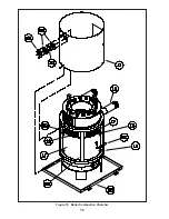
Страница 58: ...58 Figure 19 Boiler Combustion Chamber ...
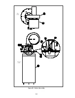
Страница 60: ...60 Figure 20 Burner Assembly FRONT VIEW TOP VIEW ...
Страница 62: ...62 Figure 21a UL FM CSD 1 Main Gas Train Assembly EVCA 750 2000 ...
Страница 64: ...64 Figure 21b UL FM CSD 1 Main Gas Train Assembly EVCA 3000 ...
Страница 66: ...66 Figure 22a DB B Gas Train 750 Figure 22b DB B Gas Train 1000 2000 ...
Страница 68: ...68 Figure 22c DB B w POC Gas Train 750 Figure 22d DB B w POC Gas Train 1000 2000 ...
Страница 70: ...70 Figure 22e DB B Gas Train EVCA 3000 Figure 22f DB B w POC Gas Train EVCA 3000 ...
Страница 72: ...72 Figure 23 Jacket ...
Страница 74: ...74 Figure 24 EVCA 750 1000 and 1500 Secondary Heat Exchanger and Housing ...
Страница 78: ...78 Figure 25b EVCA 3000 Secondary Heat Exchanger and Housing ...
Страница 80: ...80 Figure 26 Control Panel Assembly ...
Страница 82: ...82 Figure 27 Bishop Pilot Assembly ...
Страница 97: ...97 NOTES ...
Страница 98: ...98 NOTES ...
Страница 99: ...99 NOTES ...


