51
LCD Display
Alarm Message
Recommended
Action
Explanation
Remote Input Fail
Check Wiring and
Remote System
Remote Control Input Fail
The Remote Control Input is configured and is not connected or is above or be-
low a valid range. When the remote control input fails, the following control mode
changes are taken automatically:
Selected Modes Resulting Control Mode
Remote Mod Outlet Sensor and Local Setpoint
Remote Mod & Remote Sensor Remote Sensor and Local Setpoint
Remote SP Outlet Sensor and Local Setpoint
Remote SP & Remote Sensor Remote Sensor and Local Setpoint
Comm Failure
Confirm each boiler has
a unique address
Check Wiring and
Remote System
Communication Failure
The Modbus or Peer-To-Peer network has failed. When the Modbus network fails
the following control mode changes are taken automatically:
Selected Modes Resulting Control Mode
Modbus Mod
Outlet Sensor and Local Setpoint
Modbus Mod & Remote Sensor
Remote Sensor and Local Setpoint
Modbus SP
Outlet Sensor and Local Setpoint
Modbus SP & Remote Sensor
Remote Sensor and Local Setpoint
After a Modus communication failure, the ‘Comm Failure’ alarm is not cleared
until communication is restored and successfully writes to both the Remote On
/ Off Modbus Command (00004) and Remote Firing Rate or Remote Setpoint
(40006) points have been completed, power is cycled or the protocol parameter is
changed to Peer-To-Peer and then back to Modbus.
When a Peer-To-Peer network has failed the boilers begin operation as stand
alone boilers using the selected parameters.
After a Peer-To-Peer communication failure the ‘Comm Failure’ alarm is not
cleared until communication is restored and the boiler rejoins a network with at
least one other boiler, power is cycled or the protocol parameter is changed to
Modbus and then back to Peer-To-Peer.
Low Inlet Temp
Check return water
temperature. Consider
system or operational
changes to avoid low
temperature events
Check wiring and
sensor
Low Boiler Inlet Temperature
If the boiler inlet temperature is below the Low boiler inlet temperature setpoint,
the “Low Inlet Temp” Message is displayed and the boiler inlet temperature
history is stored.
Memory Failure
Call Factory Reset
all memories in
System menu:
Clr BIT History
Clr Alarm Hist
Clr Run Time Cnt
Clr Cycle Cnt
Factory Defaults
(Factory Level
Password is required)
Memory Failure
New software has been installed in the Thermal Solutions Boiler Control (TSBC)
or a power interruption has caused a memory failure. The Call For Heat will be
prevented until the condition is cleared.
TROUBLESHOOTING GUIDE (CONTINUED)
Содержание EVCA SERIES
Страница 13: ...13 Figure 3 Typical Sidewall Pressurized Venting Optional Figure 2 Typical Sidewall Pressurized Venting ...
Страница 14: ...14 Figure 4 Typical Vertical Pressurized Venting ...
Страница 16: ...16 Figure 6 Vertical Air Intake Piping Figure 5 Horizontal Air Intake Piping ...
Страница 19: ...19 Figure 8 Schematic Boiler Piping ...
Страница 25: ...25 Figure 9a 208 230 480V 1PH 3PH 60HZ Supply Power Wiring Schematic ...
Страница 26: ...26 Figure 9b 120V 1PH 60HZ Supply Power Wiring Schematic ...
Страница 27: ...27 Figure 9c Control Wiring Schematic EVCA 750 2000 ...
Страница 29: ...29 Figure 9e Control Wiring Schematic EVCA 3000 ...
Страница 32: ...32 Figure 10 Modular System Horizontal Air Intake Piping ...
Страница 33: ...33 Figure 11 Modular System Vertical Air Intake Piping ...
Страница 34: ...34 Figure 12 Modular System Typical One Pipe Water Piping ...
Страница 35: ...35 Figure 13 Modular System Typical Primary Secondary Water Piping ...
Страница 36: ...36 Figure 14 Modular System Typical Primary Secondary without System Pump ...
Страница 37: ...37 Figure 15 Modular System Typical Reverse Return Water Piping ...
Страница 38: ...38 Figure 16 Modular System Reverse Return with System Pump Only ...
Страница 39: ...39 Figure 17 Modular System Typical Primary Secondary with Reverse Return ...
Страница 55: ...55 Figure 18 Cleaning Secondary Heat Exchanger 1 2 ...
Страница 56: ...56 This page intentionally left blank ...
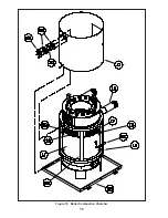
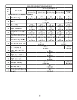
Страница 58: ...58 Figure 19 Boiler Combustion Chamber ...
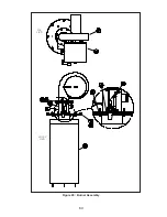
Страница 60: ...60 Figure 20 Burner Assembly FRONT VIEW TOP VIEW ...
Страница 62: ...62 Figure 21a UL FM CSD 1 Main Gas Train Assembly EVCA 750 2000 ...
Страница 64: ...64 Figure 21b UL FM CSD 1 Main Gas Train Assembly EVCA 3000 ...
Страница 66: ...66 Figure 22a DB B Gas Train 750 Figure 22b DB B Gas Train 1000 2000 ...
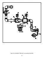
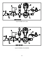
Страница 68: ...68 Figure 22c DB B w POC Gas Train 750 Figure 22d DB B w POC Gas Train 1000 2000 ...
Страница 70: ...70 Figure 22e DB B Gas Train EVCA 3000 Figure 22f DB B w POC Gas Train EVCA 3000 ...
Страница 72: ...72 Figure 23 Jacket ...
Страница 74: ...74 Figure 24 EVCA 750 1000 and 1500 Secondary Heat Exchanger and Housing ...
Страница 78: ...78 Figure 25b EVCA 3000 Secondary Heat Exchanger and Housing ...
Страница 80: ...80 Figure 26 Control Panel Assembly ...
Страница 82: ...82 Figure 27 Bishop Pilot Assembly ...
Страница 97: ...97 NOTES ...
Страница 98: ...98 NOTES ...
Страница 99: ...99 NOTES ...


