


49
A.
SAFETY AND OPERATING CONTROLS. OPERATION AND SHUT DOWN
Component
Function
Circuit Board Fuse
If the power draw of the control circuit exceeds approximately 5 amps, the circuit board
fuse trips and prevents the boiler from operating until the fuse is replaced.
Power Switch
If this switch is in the off position, power is interrupted to the control circuit of the boiler,
which prevents the boiler from operating. If the switch is in the on position, power is
supplied to the control circuit.
Operating Aquastat
If the boiler water temperature exceeds the adjustable set point, power is interrupted to
the control circuit of the boiler, which prevents the boiler from operating. When the boiler
water temperature drops below the set point minus the adjustable differential setting, power
is again supplied to the control circuit.
Manual Reset High
Limit Aquastat
If the boiler water temperature exceeds the adjustable set point, power is interrupted to the
control circuit of the boiler, which prevents the boiler from operating. Power is interrupted
until the control is manually reset by pressing the control’s reset button. When the button
is depressed, power will again be supplied to the control circuit.
Flow Switch
If the water flow through the boiler drops below the fixed flow rate required to move the
control’s paddle enough to close the controls contacts, power is interrupted to the control
circuit, which prevents the boiler from operating. When the water flow rate is increased,
the paddle closes the control’s contacts and power is supplied to the control circuit.
Pressure (Safety)
Relief Valve
If the pressure inside the appliance exceeds the fixed set point, the valve opens
mechanically and discharges water. The valve remains open until the pressure inside the
appliance drops below the set point.
Mixer Fuseable Link
If the temperature in the interior of the burner exceeds the fixed set point, The contacts of
the switch open and power is interrupted to the control circuit, which prevents the boiler
from operating. Power is interrupted until the switch is replaced.
Vestibule Fuseable
Link
If the temperature in the interior of the vestibule enclosure exceeds the fixed set point, the
contacts of the switch open and power is interrupted to the control circuit, which prevents
the boiler from operating. Power is interrupted until the switch is replaced.
High and Low Gas
Pressure Switches
If the gas pressure reaches a point below the adjustable set point, or above the adjustable
set point, the contacts of the switch open and power is interrupted to the control circuit,
which prevents the boiler from operating. Power is interrupted until gas pressure is
between the high and low set points and the control is manually reset by moving the switch
to the reset position. The switches will not reset until the gas pressure is within the set
point parameters.
Combustion Air Flow
Switch
If the differential air pressure drops below the fixed set point, the contacts of the switch
open and power is interrupted to the control circuit, which prevents the boiler from
operating. Power is interrupted until air flow increases so that the contacts close.
Flame Safeguard
Control
Refer to the manual supplied with the boiler.
Variable Frequency
Drive (VFD)
The variable frequency drive’s primary function is to vary the rotational speed of the blower
fan based on the air requirements of the boiler combustion process. The VFD responds to
a 0-10 VDC signal from the TSBC.
Thermal Solutions
Boiler Control™
(TSBC)™
The Thermal Solutions Boiler Control™ (TSBC™) is a complete boiler and automation
system. It provides advanced boiler modulation control, operating control, diagnostics,
multiple boiler lead lag and auxiliary device control. Refer to the TSBC manual shipped
with the boiler to learn more about these features and functions.
Содержание EVCA SERIES
Страница 13: ...13 Figure 3 Typical Sidewall Pressurized Venting Optional Figure 2 Typical Sidewall Pressurized Venting ...
Страница 14: ...14 Figure 4 Typical Vertical Pressurized Venting ...
Страница 16: ...16 Figure 6 Vertical Air Intake Piping Figure 5 Horizontal Air Intake Piping ...
Страница 19: ...19 Figure 8 Schematic Boiler Piping ...
Страница 25: ...25 Figure 9a 208 230 480V 1PH 3PH 60HZ Supply Power Wiring Schematic ...
Страница 26: ...26 Figure 9b 120V 1PH 60HZ Supply Power Wiring Schematic ...
Страница 27: ...27 Figure 9c Control Wiring Schematic EVCA 750 2000 ...
Страница 29: ...29 Figure 9e Control Wiring Schematic EVCA 3000 ...
Страница 32: ...32 Figure 10 Modular System Horizontal Air Intake Piping ...
Страница 33: ...33 Figure 11 Modular System Vertical Air Intake Piping ...
Страница 34: ...34 Figure 12 Modular System Typical One Pipe Water Piping ...
Страница 35: ...35 Figure 13 Modular System Typical Primary Secondary Water Piping ...
Страница 36: ...36 Figure 14 Modular System Typical Primary Secondary without System Pump ...
Страница 37: ...37 Figure 15 Modular System Typical Reverse Return Water Piping ...
Страница 38: ...38 Figure 16 Modular System Reverse Return with System Pump Only ...
Страница 39: ...39 Figure 17 Modular System Typical Primary Secondary with Reverse Return ...
Страница 55: ...55 Figure 18 Cleaning Secondary Heat Exchanger 1 2 ...
Страница 56: ...56 This page intentionally left blank ...
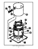
Страница 58: ...58 Figure 19 Boiler Combustion Chamber ...
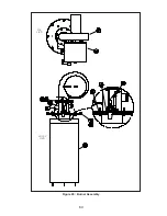
Страница 60: ...60 Figure 20 Burner Assembly FRONT VIEW TOP VIEW ...
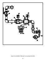
Страница 62: ...62 Figure 21a UL FM CSD 1 Main Gas Train Assembly EVCA 750 2000 ...
Страница 64: ...64 Figure 21b UL FM CSD 1 Main Gas Train Assembly EVCA 3000 ...
Страница 66: ...66 Figure 22a DB B Gas Train 750 Figure 22b DB B Gas Train 1000 2000 ...
Страница 68: ...68 Figure 22c DB B w POC Gas Train 750 Figure 22d DB B w POC Gas Train 1000 2000 ...
Страница 70: ...70 Figure 22e DB B Gas Train EVCA 3000 Figure 22f DB B w POC Gas Train EVCA 3000 ...
Страница 72: ...72 Figure 23 Jacket ...
Страница 74: ...74 Figure 24 EVCA 750 1000 and 1500 Secondary Heat Exchanger and Housing ...
Страница 78: ...78 Figure 25b EVCA 3000 Secondary Heat Exchanger and Housing ...
Страница 80: ...80 Figure 26 Control Panel Assembly ...
Страница 82: ...82 Figure 27 Bishop Pilot Assembly ...
Страница 97: ...97 NOTES ...
Страница 98: ...98 NOTES ...
Страница 99: ...99 NOTES ...


