46
VI. Boiler Operational Sequence
Sage Boiler Control Instruction Manual
Page 6 of 52
Product Features
Boiler Sequence
SI
CS
SI
CH
AL
DP
O+,O-
VI
BP
-
-
2,30
SP
25,30
70,71,
72
Outdoor Air Temp >
Warm Weather Shutdown Setpoint
-
R
el
ay
O
ut
put
s
Int
er
loc
k
In
put
s
Te
rm
ina
l N
um
be
r
Pa
ra
m
et
er/
N
ot
e
Low Fire Hold
Spare Output
Boiler Pump
System Pump
M
od
ul
at
ion
O
ut
pu
ts
Call For Heat Relay
Domestic Hot Water Priority
Flame Safeguard Alarm
Parameter / Notes
20,74
Lim
its
Inp
ut
s
9
Call For Heat
Lockout Indicator
(Manual Reset Required)
LO
-
44,30,
75
Fuel Valve Energized
Recycling Limits
(LC, OO, WF, GP and HL inputs)
Pu
m
p P
ur
ge
M
ain
Ig
nit
io
n
Low
Fi
re
H
ol
d
Pu
rg
e / P
ilo
t Ig
nit
io
n
Lo
w
F
ire
/ Ig
nit
io
n
Pu
m
p C
oo
ld
ow
n
B
oil
er
R
un
nin
g
BOILER STATE
LCD Display
System Pump Feedback
9
-
8,27,
28
-
Non-Recycling Limits
(Combustion Air Flow (CA Input))
Blower High Speed
Purge %
Modulation
Low Fire %
Blower 0 Volts
V+,V-,
P+,P-
49
52
-
9,51/f
50
R+,R-
OR
BO,BC
SO
10
System Pump Backup Pump
SO
10,27/
e
Combustion Air Damper
SO
10
System Alarm
LC, OO ,WF,
GP,HL
CA
Mixing Valve Output
MS,MR
6,79,
80
Fir
in
g
R
at
e
B
oil
er
D
is
ab
le
RO
Boiler Disable or Remote On/Off
-
-
3/d
-
-
-
53
4/d
Spare Output On
Call For Heat Relay On
Recycling Limits Made
Call For Heat
Non-Recycling Limits Made
-
W
ar
m
W
eat
her
Sh
ut
do
w
n
St
an
db
y
Lo
cko
ut
Li
m
it H
old
Combustion Air Damper Open
V+,V-,
P+,P-
V+,V-,
P+,P-
V+,V-,
P+,P-
V+,V-,
P+,P-
b &c
a
a
a
Fa
n Po
st
Pu
rg
e
54/d
Boiler Pump On
Domestic Hot Water Demand Monitored
System Pump On
System Pump Feedback Monitored
Starts in response to System Pump Feedback Input SI
Alarm Status is Monitored
Modulate
Boiler Enable/Disable On
Start/Stop Sequence States
Pre-Sequence States
Notes
a. Boiler Pump is “On” when the Boiler Pump is set to “On Always” or the boiler is lead boiler and Boiler Pump is set to “On Lead”.
b. Boiler Pump is "On" when the Boiler Pump is set to "On Always" and WWSD is set to "WWSD of System Pump" or “Off”.
c. System Pump is "On" when the System Pump is set to “yes” and WWSD is set to either "WWSD of Boiler" or "Off".
d. Boiler pump is "On" during Prepurge and Post Purge when Boiler Pump is set to "Purge" or boiler is lead & Boiler Pump is set to “On Lead”.
e. Combustion Air Damper Spare Output is maintained “On” for 2 minutes after the Call For Heat is removed.
f. Modulation rate is held at purge % when low fire input is not provided.
Содержание EVCA SERIES
Страница 13: ...13 Figure 3 Typical Sidewall Pressurized Venting Optional Figure 2 Typical Sidewall Pressurized Venting ...
Страница 14: ...14 Figure 4 Typical Vertical Pressurized Venting ...
Страница 16: ...16 Figure 6 Vertical Air Intake Piping Figure 5 Horizontal Air Intake Piping ...
Страница 19: ...19 Figure 8 Schematic Boiler Piping ...
Страница 25: ...25 Figure 9a 208 230 480V 1PH 3PH 60HZ Supply Power Wiring Schematic ...
Страница 26: ...26 Figure 9b 120V 1PH 60HZ Supply Power Wiring Schematic ...
Страница 27: ...27 Figure 9c Control Wiring Schematic EVCA 750 2000 ...
Страница 29: ...29 Figure 9e Control Wiring Schematic EVCA 3000 ...
Страница 32: ...32 Figure 10 Modular System Horizontal Air Intake Piping ...
Страница 33: ...33 Figure 11 Modular System Vertical Air Intake Piping ...
Страница 34: ...34 Figure 12 Modular System Typical One Pipe Water Piping ...
Страница 35: ...35 Figure 13 Modular System Typical Primary Secondary Water Piping ...
Страница 36: ...36 Figure 14 Modular System Typical Primary Secondary without System Pump ...
Страница 37: ...37 Figure 15 Modular System Typical Reverse Return Water Piping ...
Страница 38: ...38 Figure 16 Modular System Reverse Return with System Pump Only ...
Страница 39: ...39 Figure 17 Modular System Typical Primary Secondary with Reverse Return ...
Страница 55: ...55 Figure 18 Cleaning Secondary Heat Exchanger 1 2 ...
Страница 56: ...56 This page intentionally left blank ...
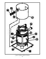
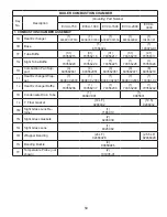
Страница 58: ...58 Figure 19 Boiler Combustion Chamber ...
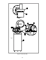
Страница 60: ...60 Figure 20 Burner Assembly FRONT VIEW TOP VIEW ...
Страница 62: ...62 Figure 21a UL FM CSD 1 Main Gas Train Assembly EVCA 750 2000 ...
Страница 64: ...64 Figure 21b UL FM CSD 1 Main Gas Train Assembly EVCA 3000 ...
Страница 66: ...66 Figure 22a DB B Gas Train 750 Figure 22b DB B Gas Train 1000 2000 ...
Страница 68: ...68 Figure 22c DB B w POC Gas Train 750 Figure 22d DB B w POC Gas Train 1000 2000 ...
Страница 70: ...70 Figure 22e DB B Gas Train EVCA 3000 Figure 22f DB B w POC Gas Train EVCA 3000 ...
Страница 72: ...72 Figure 23 Jacket ...
Страница 74: ...74 Figure 24 EVCA 750 1000 and 1500 Secondary Heat Exchanger and Housing ...
Страница 78: ...78 Figure 25b EVCA 3000 Secondary Heat Exchanger and Housing ...
Страница 80: ...80 Figure 26 Control Panel Assembly ...
Страница 82: ...82 Figure 27 Bishop Pilot Assembly ...
Страница 97: ...97 NOTES ...
Страница 98: ...98 NOTES ...
Страница 99: ...99 NOTES ...


