52
C.
PERIODIC MAINTENANCE RECOMMENDED CHECK LIST
Frequency
Component/Item
Recommended Test
Daily
Maintenance
Boiler surroundings
Inspect the area to assure proper clearance to combustible materials,
gasoline, and other flammable vapors and liquids.
Gauges, monitors, and indicators
Make visual inspection and record readings.
Combustion Properties
Check combustion properties as specified in section VII, part D.
Burner flame
Make visual inspection of burner flame as stated in section VII, part D.
Low Draft, fan air pressure, and damper
position interlocks
Test low draft, fan, air pressure, and damper position interlocks
according to instructions if so equipped.
Weekly
Maintenance
Igniter
Make visual inspection, check flame signal strength; log.
Flame signal strength
Read and log flame signal meter, read for both pilot and main flames.
Flame failure detection system
Close manual fuel supply for (1) pilot, (2) main fuel cock, and/or
valve(s); check safety shutdown timing. Refer to section VII, Part D.
Firing rate control
Check firing rate control, place TSBC™ in manual mode and check
high and low firing settings for proper operation.
Pilot and/or main fuel valves
Open limit switch and make aural and visual check; check valve
position indicators and check fuel meters if so fitted.
Low-water fuel cutoff
Test low-water fuel cutoff device and alarm according to
manufacturer’s instructions.
Monthly
Maintenance
Flue, vent, stack, condensate drains,
and outlet dampers
Confirm that components are gas tight and free from obstructions to
flow.
Gas pressure interlocks
Test high and low gas pressure interlocks.
Water condition
Test condition of water, correct condition as needed.
Semi-Annual
Maintenance
Gauges, monitors, and indicators
Recalibrate all indicating and recording gauges.
Flame failure detection system
Check components.
Condensate drain tubes
Check drain tubes have liquid in trap and condensate is properly
directed.
Air filter
Check air filter as specified in section VII, Part D.
Interlocks and valves
Check piping and wiring of all interlocks and shut off valves if so
equipped.
Circulators and system pumps
Maintain according to manufacturers' instructions.
Annual
Maintenance
Flue, vent, stack, or outlet dampers
Confirm that components are gas tight and free from obstructions to
flow.
Combustion Properties
Check combustion properties as specified in section IV, Part I, Step 5.
Flame failure detection system
Conduct pilot turndown test according to manufacturer’s instructions.
This test is required annually and after any adjustments to flame
scanner mount or pilot burner.
Pilot and/or main fuel valves
Check all coils and diaphragms; test other operating parts of all safety
shutoff and control valves.
Pilot and/or main fuel valves
Perform leakage test on pilot and main gas and/or oil fuel valves, in
accordance with instructions.
Flame safeguard
Test purge timing according to manufacturer’s instructions.
Air Filter
Replace
Boiler trim
Remove lower front jacket panel and check for any signs of corrosion
and leaks.
Secondary Heat Exchanger
Check and clean if dirty. Refer to section VII, Part D.
High limit and operating temp. controls
Test proper operation.
Mixing Valve
Test proper operation. Refer to section VII, Part D.
As-Required
Low-water fuel cutoff
Recondition or replace.
Safety relief valves
Test safety relief valves in accordance with ASME Boiler and Pressure
Vessel Code, Sections VI and VII.
Содержание EVCA SERIES
Страница 13: ...13 Figure 3 Typical Sidewall Pressurized Venting Optional Figure 2 Typical Sidewall Pressurized Venting ...
Страница 14: ...14 Figure 4 Typical Vertical Pressurized Venting ...
Страница 16: ...16 Figure 6 Vertical Air Intake Piping Figure 5 Horizontal Air Intake Piping ...
Страница 19: ...19 Figure 8 Schematic Boiler Piping ...
Страница 25: ...25 Figure 9a 208 230 480V 1PH 3PH 60HZ Supply Power Wiring Schematic ...
Страница 26: ...26 Figure 9b 120V 1PH 60HZ Supply Power Wiring Schematic ...
Страница 27: ...27 Figure 9c Control Wiring Schematic EVCA 750 2000 ...
Страница 29: ...29 Figure 9e Control Wiring Schematic EVCA 3000 ...
Страница 32: ...32 Figure 10 Modular System Horizontal Air Intake Piping ...
Страница 33: ...33 Figure 11 Modular System Vertical Air Intake Piping ...
Страница 34: ...34 Figure 12 Modular System Typical One Pipe Water Piping ...
Страница 35: ...35 Figure 13 Modular System Typical Primary Secondary Water Piping ...
Страница 36: ...36 Figure 14 Modular System Typical Primary Secondary without System Pump ...
Страница 37: ...37 Figure 15 Modular System Typical Reverse Return Water Piping ...
Страница 38: ...38 Figure 16 Modular System Reverse Return with System Pump Only ...
Страница 39: ...39 Figure 17 Modular System Typical Primary Secondary with Reverse Return ...
Страница 55: ...55 Figure 18 Cleaning Secondary Heat Exchanger 1 2 ...
Страница 56: ...56 This page intentionally left blank ...
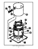
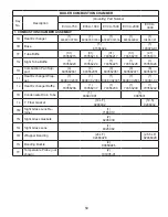
Страница 58: ...58 Figure 19 Boiler Combustion Chamber ...
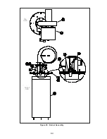
Страница 60: ...60 Figure 20 Burner Assembly FRONT VIEW TOP VIEW ...
Страница 62: ...62 Figure 21a UL FM CSD 1 Main Gas Train Assembly EVCA 750 2000 ...
Страница 64: ...64 Figure 21b UL FM CSD 1 Main Gas Train Assembly EVCA 3000 ...
Страница 66: ...66 Figure 22a DB B Gas Train 750 Figure 22b DB B Gas Train 1000 2000 ...
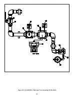
Страница 68: ...68 Figure 22c DB B w POC Gas Train 750 Figure 22d DB B w POC Gas Train 1000 2000 ...
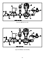
Страница 70: ...70 Figure 22e DB B Gas Train EVCA 3000 Figure 22f DB B w POC Gas Train EVCA 3000 ...
Страница 72: ...72 Figure 23 Jacket ...
Страница 74: ...74 Figure 24 EVCA 750 1000 and 1500 Secondary Heat Exchanger and Housing ...
Страница 78: ...78 Figure 25b EVCA 3000 Secondary Heat Exchanger and Housing ...
Страница 80: ...80 Figure 26 Control Panel Assembly ...
Страница 82: ...82 Figure 27 Bishop Pilot Assembly ...
Страница 97: ...97 NOTES ...
Страница 98: ...98 NOTES ...
Страница 99: ...99 NOTES ...


