47
Sage Boiler Control Instruction Manual
Page 7 of 52
Product Features
Boiler Sequence (Continued)
Pre-Sequence States
BOILER
STATE
LCD Display
CONTROL MODE
LCD Display
Description
Boiler
Disabled
Any Mode
(Except for
Remote Control)
Boiler is prevented from starting, Remote On/Off (Enable) (Terminal RO) Input is not
energized.
Warm
Weather
Shutdown
Any Mode
(Except for
Manual Mode)
Boiler is prevented from starting, Warm Weather Shutdown (WWSD) is enabled and
outside air temperature is above the WWSD Setpoint.
Lockout
Any Mode
Boiler is prevented from starting, Flame Safeguard lockout is present. A Flame
Safeguard manual reset is required.
Outlet Sensor &
Local SP Mode
Control monitors boiler outlet temperature, a Call For Heat is initiated when boiler
outlet temperature is below the Operational Setpoint.
Remote Sensor
& Local SP
Mode
Control monitors Remote System Temperature, a Call For Heat is initiated when
Remote System Temperature is below the Operational Setpoint.
Outlet Sensor &
Remote SP
Mode
Control monitors boiler outlet temperature, a Call For Heat is initiated when boiler
outlet temperature is below the Remote Setpoint Input (Terminal C+,C- or Modbus
Interface).
Remote Sensor
& Remote SP
Mode
Control monitors Remote System Temperature, a Call For Heat is initiated when
Remote System Temperature is below the Remote Setpoint Input (terminal C+,C- or
Modbus Interface).
Remote Control
Mode
Control monitors Remote On/Off (Enable) input (Terminal RO or Modbus Interface), a
Call For Heat is initiated when input is energized.
Standby
Manual
Operation Mode A Call For Heat is initiated when Manual Mode Menu item Boiler On/Off is set to On.
Start/Stop Sequence States
BOILER
STATE
LCD Display
CONTROL MODE
LCD Display
Description
Pump Purge
Any Mode
(Except
Manual Mode)
Once a Call For Heat is initiated and Boiler Pump Purge is selected, the pump output
is energized until the Pump Prepurge Time is complete. If the Call For Heat condition
still exists at the end of the Prepurge Time (the temperature of the water at the sensor
may rise with boiler water flowing passed it) the pump will continue to operate and the
Call For Heat Relay is energized.
Limit Hold
Any Mode
Power is applied to the safety limit string. If any limits does not pass power (is not
energized), the alarm LED and LCD display shows the reason the start sequence is
on Hold. Refer to Trouble shooting section for explanation of individual lockout and
alarm messages.
Purge / Pilot
Ignition
Any Mode
After the limit string passes power, the fan is started, the modulation output is set to
Purge Rate. When the purge period is complete, the flame safeguard sequences on
the ignition transformer and pilot.
Low Fire /
Ignition
Any Mode
When the Spare Input Low Fire is selected, modulation output is set to the Low Fire
Speed when the Spare Input is energized.
Main Ignition
Any Mode
The main gas valve input is energized and the modulation output is held constant for
an ignition stabilization period.
Low Fire
Hold
Any Mode
The modulation output is held at the Low Fire for the Low Fire Hold time.
Boiler
Running
Any Mode
When this Low Fire Hold time is complete, the modulation output is released to
modulate.
Fan Post
Purge
Any Mode
When water temperature is above setpoint, there is a Flame Safeguard or Limit fault,
the Call For Heat is ended and the modulating output is set to Purge Rate for the Post
Purge Time.
Pump
Cooldown
Any Mode
When Boiler Pump Purge is selected, the boiler pump remains “on” until the boiler
outlet temperature is less than the Post Purge Delta (default is 5 F) above the Boiler
Inlet Temperature.
Содержание EVCA SERIES
Страница 13: ...13 Figure 3 Typical Sidewall Pressurized Venting Optional Figure 2 Typical Sidewall Pressurized Venting ...
Страница 14: ...14 Figure 4 Typical Vertical Pressurized Venting ...
Страница 16: ...16 Figure 6 Vertical Air Intake Piping Figure 5 Horizontal Air Intake Piping ...
Страница 19: ...19 Figure 8 Schematic Boiler Piping ...
Страница 25: ...25 Figure 9a 208 230 480V 1PH 3PH 60HZ Supply Power Wiring Schematic ...
Страница 26: ...26 Figure 9b 120V 1PH 60HZ Supply Power Wiring Schematic ...
Страница 27: ...27 Figure 9c Control Wiring Schematic EVCA 750 2000 ...
Страница 29: ...29 Figure 9e Control Wiring Schematic EVCA 3000 ...
Страница 32: ...32 Figure 10 Modular System Horizontal Air Intake Piping ...
Страница 33: ...33 Figure 11 Modular System Vertical Air Intake Piping ...
Страница 34: ...34 Figure 12 Modular System Typical One Pipe Water Piping ...
Страница 35: ...35 Figure 13 Modular System Typical Primary Secondary Water Piping ...
Страница 36: ...36 Figure 14 Modular System Typical Primary Secondary without System Pump ...
Страница 37: ...37 Figure 15 Modular System Typical Reverse Return Water Piping ...
Страница 38: ...38 Figure 16 Modular System Reverse Return with System Pump Only ...
Страница 39: ...39 Figure 17 Modular System Typical Primary Secondary with Reverse Return ...
Страница 55: ...55 Figure 18 Cleaning Secondary Heat Exchanger 1 2 ...
Страница 56: ...56 This page intentionally left blank ...
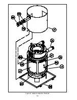
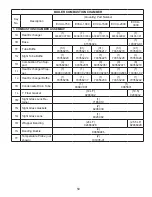
Страница 58: ...58 Figure 19 Boiler Combustion Chamber ...
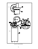
Страница 60: ...60 Figure 20 Burner Assembly FRONT VIEW TOP VIEW ...
Страница 62: ...62 Figure 21a UL FM CSD 1 Main Gas Train Assembly EVCA 750 2000 ...
Страница 64: ...64 Figure 21b UL FM CSD 1 Main Gas Train Assembly EVCA 3000 ...
Страница 66: ...66 Figure 22a DB B Gas Train 750 Figure 22b DB B Gas Train 1000 2000 ...
Страница 68: ...68 Figure 22c DB B w POC Gas Train 750 Figure 22d DB B w POC Gas Train 1000 2000 ...
Страница 70: ...70 Figure 22e DB B Gas Train EVCA 3000 Figure 22f DB B w POC Gas Train EVCA 3000 ...
Страница 72: ...72 Figure 23 Jacket ...
Страница 74: ...74 Figure 24 EVCA 750 1000 and 1500 Secondary Heat Exchanger and Housing ...
Страница 78: ...78 Figure 25b EVCA 3000 Secondary Heat Exchanger and Housing ...
Страница 80: ...80 Figure 26 Control Panel Assembly ...
Страница 82: ...82 Figure 27 Bishop Pilot Assembly ...
Страница 97: ...97 NOTES ...
Страница 98: ...98 NOTES ...
Страница 99: ...99 NOTES ...


