


67
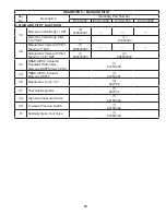
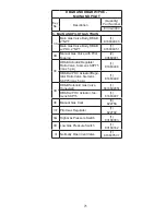
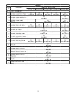
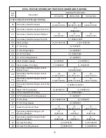
DB&B – MAIN AND PILOT
Key
No.
Description
(Quantity) Part Number
EVCA-750
EVCA-1000
EVCA-1500
EVCA-2000
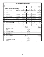
3. MAIN AND PILOT GAS TRAIN
3A
Main Gas Valve Body 1" NPT
(1)
816634041
—
—
—
Main Gas Valve Body, DBL,
1-1/2" NPT
—
(1)
81663404
3B
Manual Gas Valve with Pilot
Tapping, 1" NPT
(1)
806603055
—
—
—
Manual Gas Valve with Pilot
Tapping, 1-1/2" NPT
(1)
806603053
(2)
806603053
3C
DB&B Actuator/Regulator
Ratio Valve, Siemens SKP75
(max 5 PSI)
(1)
81663408
3D
DB&B Solenoid Valve
(1)
81660207
(1)
81660205
3E
Manual Gas Cock, 1/4"
(3)
822758
3F
Pilot Gas Regulator
(1)
822702
3G
High Gas Pressure Switch
(1)
80160333
3H
Low Gas Pressure Switch
(1)
80160332
3I
Normally Open Vent Valve
(1)
81660748
Содержание EVCA SERIES
Страница 13: ...13 Figure 3 Typical Sidewall Pressurized Venting Optional Figure 2 Typical Sidewall Pressurized Venting ...
Страница 14: ...14 Figure 4 Typical Vertical Pressurized Venting ...
Страница 16: ...16 Figure 6 Vertical Air Intake Piping Figure 5 Horizontal Air Intake Piping ...
Страница 19: ...19 Figure 8 Schematic Boiler Piping ...
Страница 25: ...25 Figure 9a 208 230 480V 1PH 3PH 60HZ Supply Power Wiring Schematic ...
Страница 26: ...26 Figure 9b 120V 1PH 60HZ Supply Power Wiring Schematic ...
Страница 27: ...27 Figure 9c Control Wiring Schematic EVCA 750 2000 ...
Страница 29: ...29 Figure 9e Control Wiring Schematic EVCA 3000 ...
Страница 32: ...32 Figure 10 Modular System Horizontal Air Intake Piping ...
Страница 33: ...33 Figure 11 Modular System Vertical Air Intake Piping ...
Страница 34: ...34 Figure 12 Modular System Typical One Pipe Water Piping ...
Страница 35: ...35 Figure 13 Modular System Typical Primary Secondary Water Piping ...
Страница 36: ...36 Figure 14 Modular System Typical Primary Secondary without System Pump ...
Страница 37: ...37 Figure 15 Modular System Typical Reverse Return Water Piping ...
Страница 38: ...38 Figure 16 Modular System Reverse Return with System Pump Only ...
Страница 39: ...39 Figure 17 Modular System Typical Primary Secondary with Reverse Return ...
Страница 55: ...55 Figure 18 Cleaning Secondary Heat Exchanger 1 2 ...
Страница 56: ...56 This page intentionally left blank ...
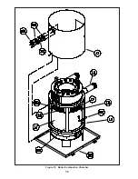
Страница 58: ...58 Figure 19 Boiler Combustion Chamber ...
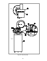
Страница 60: ...60 Figure 20 Burner Assembly FRONT VIEW TOP VIEW ...
Страница 62: ...62 Figure 21a UL FM CSD 1 Main Gas Train Assembly EVCA 750 2000 ...
Страница 64: ...64 Figure 21b UL FM CSD 1 Main Gas Train Assembly EVCA 3000 ...
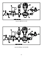
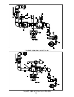
Страница 66: ...66 Figure 22a DB B Gas Train 750 Figure 22b DB B Gas Train 1000 2000 ...
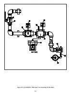
Страница 68: ...68 Figure 22c DB B w POC Gas Train 750 Figure 22d DB B w POC Gas Train 1000 2000 ...
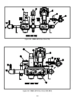
Страница 70: ...70 Figure 22e DB B Gas Train EVCA 3000 Figure 22f DB B w POC Gas Train EVCA 3000 ...
Страница 72: ...72 Figure 23 Jacket ...
Страница 74: ...74 Figure 24 EVCA 750 1000 and 1500 Secondary Heat Exchanger and Housing ...
Страница 78: ...78 Figure 25b EVCA 3000 Secondary Heat Exchanger and Housing ...
Страница 80: ...80 Figure 26 Control Panel Assembly ...
Страница 82: ...82 Figure 27 Bishop Pilot Assembly ...
Страница 97: ...97 NOTES ...
Страница 98: ...98 NOTES ...
Страница 99: ...99 NOTES ...


