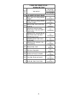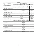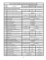
85
IX. Thermal Solutions Boiler Control™ (TSBC™)
A.
INTRODUCTION -
The intent of this section is to briefly summarize the controllers capabilities, familiarize the user with its
basic features and to list the factory supplied default settings. Read the additionally supplied Factory Instruction Manual for
the TSBC to learn more about the controllers features and capabilities.
1.
Thermal Solutions Boiler Control™ Overview
The Thermal Solutions Boiler Control
™
(TSBC
™
) is a complete boiler monitoring and automation system. The TSBC
™
provides advanced boiler modulation, operating control, diagnostics, multiple boiler lead-lag and auxiliary device control.
The TSBC
™
provides advanced control features in an easy to use package.
2.
Flexible, Field Selectable Control
Control modes, water system, boiler auxiliary
and modulating lead/lag control features are
menu selectable without the need for external
programmers, lap tops or down loads. Every boiler
is shipped with factory defaults that make field
menu selections unnecessary unless you are applying
additional control features.
3.
Boiler Monitoring and Diagnostic Displays
The TSBC
™
's two line by sixteen character LCD
display may be used for monitoring boiler inlet and
outlet, remote system and outside air temperatures,
modulation rate setpoint and modulating percent
and mixing valve demand percent. Additionally,
the display automatically presents boiler sequence
messages, alarms, hold and lockout messages. A
diagnostic menu is included that provides the last
10 alarm messages and boiler inlet temperature
alarm history. Boiler inlet temperature alarm history
includes time and date, the lowest inlet temperature
reached and the amount of time the water
temperature dropped below the alarm setpoint.
4.
Modulation Rate and On/Off Modes
The TSBC
™
may simply control boiler modulation
and on/off output based on the boiler water outlet
temperature and an operator adjusted setpoint.
However, using parameter selections, the TSBC™
allows the boiler modulation and on/off output
to respond to remote system water and outside
air temperatures, Domestic Hot Water Priority
(DHWP) input or Energy Domestic Hot Water
Priority (EMS) modulation rate demand, remote
setpoint or remote start/stop commands. Parameter
selections of remote system water temperature and
remote mode determine the choice of one of six
different control modes.
5.
Advanced Availability
The above control modes are menu selectable
options. However, if a selected sensor fails, the
TSBC
™
automatically changes to a control mode
that will allow continued automatic operation of
the boiler. For example, in the event of a remote
system temperature sensor failure, the TSBC
™
will
automatically switch to boiler outlet temperature
sensor based control.
6.
Outdoor Air Reset
When selected the modulation rate setpoint
is automatically adjusted based on outside air
temperature. Outdoor air "reset" setpoint saves
fuel by adjusting the water temperature of a heating
boiler lower as the outside air temperature increases.
7.
Warm Weather Shutdown (WWSD)
Some boilers are used primarily for heating
buildings, and the boilers can be automatically
shutdown when the outdoor air temperature is
warm. When outside air temperature is above the
WWSD setpoint, this function will prevent the
boiler, boiler pump and/or the system pump from
starting.
8.
Domestic Hot Water Priority (DHWP)
Some boilers are used primarily for building space
heating, but also provide heat for the domestic hot
water users. When the outdoor temperature is
warm, the outdoor reset setpoint may drop lower
than a desirable domestic hot water temperature.
When enabled and a DHWP contact input is
detected, the hot water setpoint is adjusted to be
greater than a field adjustable DHWP Setpoint.
9.
Water Side Control Outputs
In order to maximize the life and availability of a
hot water systems it may be desirable to automate
mixing valves, boiler pumps, system pumps, and
standby system pumps. The TSBC
™
makes this
type of automation totally integrated and cost
effective. The control of these devices is field
selectable through simple yes/no menu selections.
10.
Combustion Air Side Control Outputs
Boiler room Combustion air dampers (fresh air
dampers) and Vent Inducer control outputs are field
selectable options.
11.
Peer-To-Peer Network
The TSBC
™
includes state-of-the-art modulating
lead-lag sequencer for up to eight (8) boilers capable
of auto rotation, outdoor reset and peer-to-peer
communication. The peer-to-peer network is truly
"plug and play". Communication is activated by
simply connecting a RJ11 telephone line between
boilers. The TSBC
™
provides precise boiler
coordination by sequencing boilers based on
Содержание EVCA SERIES
Страница 13: ...13 Figure 3 Typical Sidewall Pressurized Venting Optional Figure 2 Typical Sidewall Pressurized Venting ...
Страница 14: ...14 Figure 4 Typical Vertical Pressurized Venting ...
Страница 16: ...16 Figure 6 Vertical Air Intake Piping Figure 5 Horizontal Air Intake Piping ...
Страница 19: ...19 Figure 8 Schematic Boiler Piping ...
Страница 25: ...25 Figure 9a 208 230 480V 1PH 3PH 60HZ Supply Power Wiring Schematic ...
Страница 26: ...26 Figure 9b 120V 1PH 60HZ Supply Power Wiring Schematic ...
Страница 27: ...27 Figure 9c Control Wiring Schematic EVCA 750 2000 ...
Страница 29: ...29 Figure 9e Control Wiring Schematic EVCA 3000 ...
Страница 32: ...32 Figure 10 Modular System Horizontal Air Intake Piping ...
Страница 33: ...33 Figure 11 Modular System Vertical Air Intake Piping ...
Страница 34: ...34 Figure 12 Modular System Typical One Pipe Water Piping ...
Страница 35: ...35 Figure 13 Modular System Typical Primary Secondary Water Piping ...
Страница 36: ...36 Figure 14 Modular System Typical Primary Secondary without System Pump ...
Страница 37: ...37 Figure 15 Modular System Typical Reverse Return Water Piping ...
Страница 38: ...38 Figure 16 Modular System Reverse Return with System Pump Only ...
Страница 39: ...39 Figure 17 Modular System Typical Primary Secondary with Reverse Return ...
Страница 55: ...55 Figure 18 Cleaning Secondary Heat Exchanger 1 2 ...
Страница 56: ...56 This page intentionally left blank ...
Страница 58: ...58 Figure 19 Boiler Combustion Chamber ...
Страница 60: ...60 Figure 20 Burner Assembly FRONT VIEW TOP VIEW ...
Страница 62: ...62 Figure 21a UL FM CSD 1 Main Gas Train Assembly EVCA 750 2000 ...
Страница 64: ...64 Figure 21b UL FM CSD 1 Main Gas Train Assembly EVCA 3000 ...
Страница 66: ...66 Figure 22a DB B Gas Train 750 Figure 22b DB B Gas Train 1000 2000 ...
Страница 68: ...68 Figure 22c DB B w POC Gas Train 750 Figure 22d DB B w POC Gas Train 1000 2000 ...
Страница 70: ...70 Figure 22e DB B Gas Train EVCA 3000 Figure 22f DB B w POC Gas Train EVCA 3000 ...
Страница 72: ...72 Figure 23 Jacket ...
Страница 74: ...74 Figure 24 EVCA 750 1000 and 1500 Secondary Heat Exchanger and Housing ...
Страница 78: ...78 Figure 25b EVCA 3000 Secondary Heat Exchanger and Housing ...
Страница 80: ...80 Figure 26 Control Panel Assembly ...
Страница 82: ...82 Figure 27 Bishop Pilot Assembly ...
Страница 97: ...97 NOTES ...
Страница 98: ...98 NOTES ...
Страница 99: ...99 NOTES ...


