


Theory of Operation—DM 5010
Initially, as the power module is turned on, the PWR MOL
line
is held low for a short time. This keeps Q1105 and
Q1104
turned off, holding
the output of U1000 high. This
keeps
Q1101 and the series-pass transistor in the power
module turned off.
Then the PWR
MDL
line goes high
and Q1105 is turned
on. This forward biases Q1104,
allowing current to flow
through Zener diode VR1001. The inverting input of U1000
is now held at
+5 volts and its output goes negative, turn
ing on Q1101. As Q1101 comes on, base current begins to
flow in the series-pass transistor to
turn it on.
primary
winding
connected to the power module’s +25 V
supply,
the
ends of
the primary coil are alternately switched
to
ground at an approximate 27.78 kHz rate. This rate is
synchronized
to the A/D conversion process and
minimizes
any
converter error caused by power
supply ripple in the
Isolated Section.
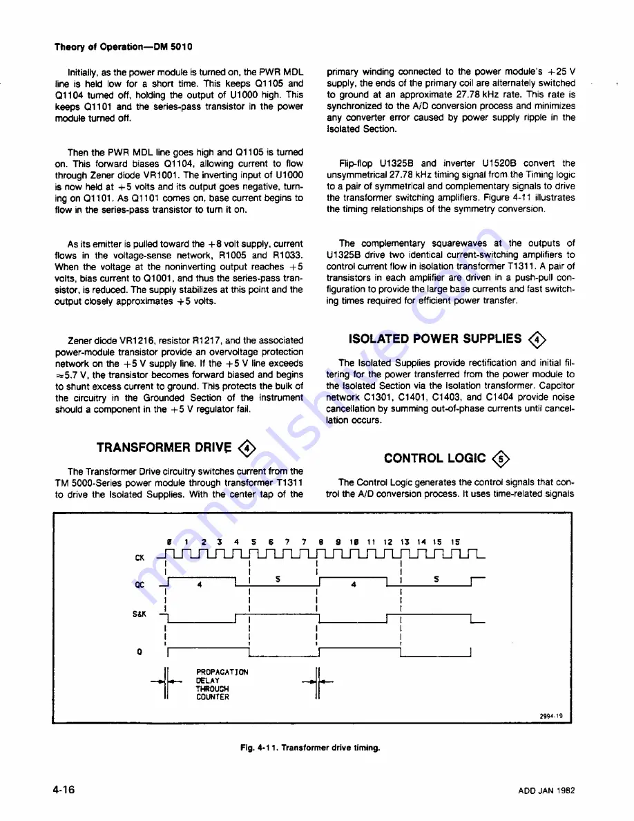
Flip-flop
U1325B
and inverter U1520B convert the
unsymmetrical 27,78 kHz
timing signal from the Timing logic
to
a pair of symmetrical and complementary
signals to drive
the transformer
switching
amplifiers.
Figure 4-11 illustrates
the timing relationships of the symmetry conversion.
As
its emitter is pulled toward
the
+8 volt supply, current
flows
in the voltage-sense network,
R1005 and R1033.
When
the voltage at the noninverting output r5
volts,
bias current to Q1001,
and thus the series-pass tran
sistor,
is
reduced. The supply stabilizes at this point and the
output closely approximates
+5 volts.
The complementary squarewaves
at the
outputs of
U1325B
drive
two identical current-switching amplifiers to
control
current
flow
in isolation transformer T1311. A pair of
transistors
in each amplifier are driven in a push-pull con
figuration to provide the large base currents and fast switch
ing
times required for efficient power transfer.
Zener diode VR1216, resistor R1217, and
the associated
power-module
transistor provide
an overvoltage protection
network
on the
+5 V supply line. If the +5 V line exceeds
¾5.7 V, the transistor becomes forward biased
and begins
to
shunt
excess current to ground. This protects the bulk of
the
circuitry
in the Grounded Section of the instrument
should
a component
in the
+5 V regulator fail.
TRANSFORMER
DRIVE <4>
The Transformer Drive circuitry switches current from the
TM
5000-Series
power module through transformer T1311
to
drive the Isolated
Supplies. With
the center tap of the
ISOLATED POWER SUPPLIES
<4>
The
Isolated Supplies provide rectification and initial fil
tering for the
power transferred
from the power module to
the Isolated
Section via the Isolation transformer. Capcitor
network C1301, C1401,
C1403, and
C1404 provide noise
cancellation by summing
out-of-phase currents until cancel
lation
occurs.
CONTROL
LOGIC
<5>
The Control Logic generates the control signals that con
trol
the A/D
conversion process. It uses time-related signals
jnjnjnjnjnjnjnjnjnj“Ljnjnjnjnjnjnj
-
LrLrL
n---------------i_________ n-------------- 1__
I------------------ 1________ I-------------------1________ I
PROPACATJON
■»
—
DELAY
THROUGH
COUNTER
299419
Fig. 4-11. Transformer drive timing.
4-16
ADD
JAN
1982
Содержание DM 5010
Страница 14: ...DM 5010 2994 00 DM 5010 Programmable Digital Multimeter xii ADD JUL 1986...
Страница 27: ...Operating Instructions DM 5010 2994 03 Fig 2 3 DM 5010 front panel controls and connectors 2 3...
Страница 38: ......
Страница 40: ...Programming DM 5010 2994 07 Fig 3 1 instrument commands and relationship to front panel controls 3 2...
Страница 101: ...Theory of Operation DM 5010 SOURCE ACCEPTOR 2874 1 50A Fig 4 15 GP B Handshake flowchart ADD JAN 1982 4 27...
Страница 134: ......
Страница 208: ......
Страница 222: ......
Страница 250: ......
Страница 251: ...Section 8 DM 5010 OPTIONS No options are available 8 1...
Страница 252: ......
Страница 270: ......
Страница 272: ...DM 5010 2994 37 Fig 10 2 Location of DM 5010 adjustments and test points...
Страница 273: ......
Страница 274: ......
Страница 275: ......
Страница 276: ...DM 5010 2994 112 DM 5010 BLOCK DIAGRAM...
Страница 281: ......
Страница 282: ......
Страница 291: ......
Страница 293: ......
Страница 294: ......
Страница 297: ......
Страница 298: ......
Страница 303: ......
Страница 304: ...I...
Страница 305: ......
Страница 310: ......
Страница 311: ......
Страница 315: ......
Страница 318: ......
Страница 321: ......
Страница 323: ......
Страница 326: ......
Страница 332: ...2994 57...
Страница 334: ......
Страница 335: ......
Страница 336: ......
Страница 337: ...63 REV JUN 1986...
Страница 338: ...FIG 1 EXPLODED DM 5010...
Страница 339: ......
Страница 340: ......
Страница 341: ......
Страница 347: ......


