


Instructions
d
’
utilisation - DM
5010
COMMANDES ET CONNECTEURS
DELA
FACE
AVANT
Informations générales
Les 1
7
boutons
poussoirs de la
face avant indiqués ci-
dessous
correspondent chacun à une fonction de
l
’
instrument.
Ils
s'allument une fois enfoncés. Les bou
tons de la colonne de gauche s'annulent respectivement
:
un
seul
bouton est allumé à la fois.
Les boutons de la
colonne
de
droite restent allumés jusqu’à ce qu’on les
enfonce
de nouveau.
DCV
NULL
OHMS
LOW
FREQ
RESPONSE
DIODE
TEST
AUTO
ACV
RUN
ACV
+ DCV
TRIGGERED
FAST
AVERAGE
X-B
A
dBm
dBr
COMPARE
REAR
INPUT
Les boutons poussoirs
restants (23)
ne s’allument
pas.
Voir
figure 2.2.
Fenêtre
d’affichage
La
partie gauche de
la fenêtre contient les mesures et
les
résultats des calculs affichés sur
4
chiffres
et demi
(DELs).
Les zéros à gauche du point décimal sont sup
primés.
Un clignotement
indique
un
dépassement de
gamme
au
cours d’une mesure de
tension.
“OC" est
affiché
pour les fonctions OHMS
et DIODE TEST.
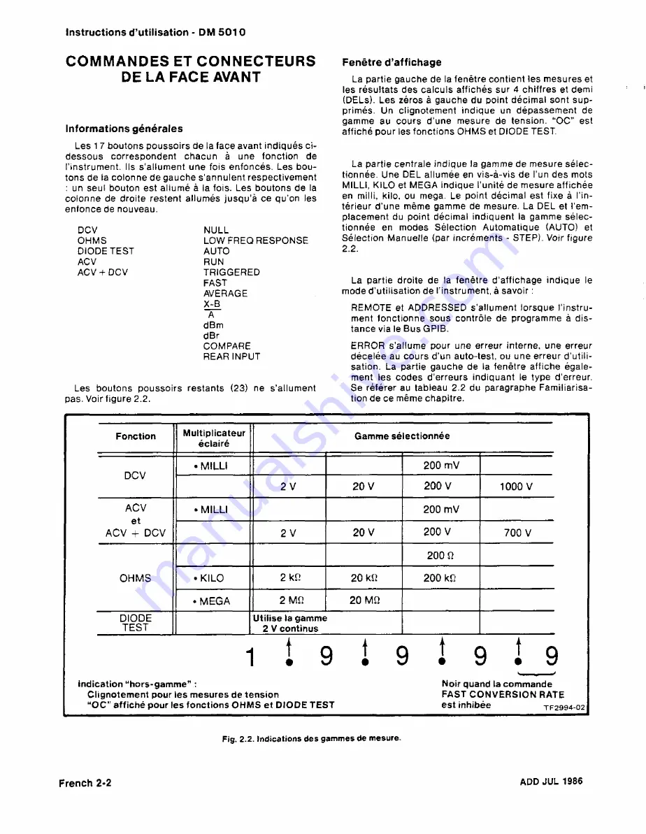
La
partie
centrale
indique la gamme de mesure sélec
tionnée.
Une DEL allumée en vis-à-vis de l’un des mots
MILLI, KILO et MEGA indique l’unité de mesure affichée
en milli, kilo,
ou mega. Le point décimal est fixe à l’in
térieur
d’une
même gamme de mesure. La DEL et rem
placement
du point
décimal
indiquent la gamme sélec
tionnée
en modes Sélection Automatique (AUTO) et
Sélection
Manuelle (par incréments - STEP). Voir figure
2.2.
La partie droite de la fenêtre d'affichage indique le
mode d’utilisation de l’instrument,
à savoir :
REMOTE et ADDRESSED
s’allument lorsque l’instru
ment
fonctionne sous contrôle de programme à dis
tance via
le Bus GPIB.
ERROR
s'allume
pour une erreur interne, une erreur
décelée au cours d’
un auto-test, ou une erreur d’utili
sation.
La partie
gauche de la fenêtre affiche égale
ment
les codes d’erreurs
indiquant le
type d’erreur.
Se
référer au
tableau 2.2 du paragraphe Familiarisa
tion de
ce même
chapitre.
Fonction
Multiplicateur
éclairé
Gamme
sé lectionnée
DCV
•
MILLI
200 mV
2
V
20
V
200 V
1000
V
ACV
et
ACV
+
DCV
•
MILLI
200
mV
2
V
20
V
200
V
700
V
OHMS
200 Ω
•
KILO
2
kΩ
20
kΩ
200
kΩ
•MEGA
2
MΩ
20
MΩ
DIODE
TEST
Utilise
la
gamme
2 V continus
indication “hors-gamme
”
:
Clignotement
pour
les mesures de tension
“
OC" affiché
pour
les fonctions OHMS et DIODE
TEST
l...
,
Noir
quand
la commande
FAST CONVERSION RATE
est
inhibée
tf
2994 02
Fig.
2.2.
Indications des
gammes de mesure.
French
2-2
ADD
JUL
1986
Содержание DM 5010
Страница 14: ...DM 5010 2994 00 DM 5010 Programmable Digital Multimeter xii ADD JUL 1986...
Страница 27: ...Operating Instructions DM 5010 2994 03 Fig 2 3 DM 5010 front panel controls and connectors 2 3...
Страница 38: ......
Страница 40: ...Programming DM 5010 2994 07 Fig 3 1 instrument commands and relationship to front panel controls 3 2...
Страница 101: ...Theory of Operation DM 5010 SOURCE ACCEPTOR 2874 1 50A Fig 4 15 GP B Handshake flowchart ADD JAN 1982 4 27...
Страница 134: ......
Страница 208: ......
Страница 222: ......
Страница 250: ......
Страница 251: ...Section 8 DM 5010 OPTIONS No options are available 8 1...
Страница 252: ......
Страница 270: ......
Страница 272: ...DM 5010 2994 37 Fig 10 2 Location of DM 5010 adjustments and test points...
Страница 273: ......
Страница 274: ......
Страница 275: ......
Страница 276: ...DM 5010 2994 112 DM 5010 BLOCK DIAGRAM...
Страница 281: ......
Страница 282: ......
Страница 291: ......
Страница 293: ......
Страница 294: ......
Страница 297: ......
Страница 298: ......
Страница 303: ......
Страница 304: ...I...
Страница 305: ......
Страница 310: ......
Страница 311: ......
Страница 315: ......
Страница 318: ......
Страница 321: ......
Страница 323: ......
Страница 326: ......
Страница 332: ...2994 57...
Страница 334: ......
Страница 335: ......
Страница 336: ......
Страница 337: ...63 REV JUN 1986...
Страница 338: ...FIG 1 EXPLODED DM 5010...
Страница 339: ......
Страница 340: ......
Страница 341: ......
Страница 347: ......


