7 Teleservice Application Framework
User Manual
111/374
Low Level Hardware Access
LED
Path
Input
information
Output
information
Description
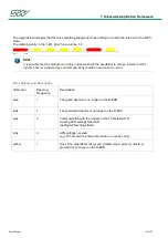
User LED
/tmp/LED_User
p1 p2
-
This file includes the parameters of the
'User' states
p1: defines the color of the LED
< 1 > = red
< 2 > = green
< 3 > = yellow
< 4 > = blue
< 5 > = pink
< 6 > = cyan
< 7 > = white
p2: defines how often the signal should
flash
< 0 > = ON for 2 seconds
< 1 > = flash 1 time
< x > = flash x times
STW LED
/tmp/LED_Error
p1 p2
-
This file includes the parameters for the
'Error' states
p1: defines the color of the LED
< 2 > = green
< 3 > = yellow
< 4 > = blue
< 5 > = pink
< 6 > = cyan
< 7 > = white
p2: defines how often the signal should
flash
< 1 > = flash 1 time
< x > = flash x times
NOTE:
If the parameters of the LED_User/LED_Error file deviate from the description above, the file will not
be taken into account.
Содержание TC1
Страница 1: ...TC1 User Manual Version of this document V1 00r0 ...
Страница 25: ...5 Hardware User Manual 25 374 5 2 2 Block Diagram Variant TC1 WIFI ...
Страница 34: ...5 Hardware User Manual 34 374 5 6 Housing Connector Top view and side view Bottom View ...
Страница 125: ...7 Teleservice Application Framework User Manual 125 374 TAF overview ...
Страница 174: ...7 Teleservice Application Framework User Manual 174 374 ADDRESS 6 SIZE 4 TYPE UINT32 UNIT COMMENT EnginePower ...
Страница 190: ...7 Teleservice Application Framework User Manual 190 374 How the logger mechanism works ...
Страница 223: ...7 Teleservice Application Framework User Manual 223 374 Association between logic hysteresis and threshold ...
Страница 293: ...8 Development Tools User Manual 293 374 3 Adapt the Build Options in order to build the binary with debug symbols ...
Страница 302: ...8 Development Tools User Manual 302 374 2 Adapt the Build Options in order to build the binary with debug symbols ...

