BM55
aligned keyways and center it on sprocket.
Do not
tighten set screws at this time!
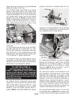
13) “Carefully” rotate engine back to it’s original
position. Slip #1804 Chain over #1801 Drive
Sprocket and engage teeth. Relocate Engine over
original mounting holes. From “above” replace the
four Flange Bolts, “below secure with original
Washers and Locknuts.
Before
Locknuts start to
tighten, locate Engine by pushing it “toward” &
“parallel” to the “left” Body Wall as far as it will go.
Then, without twisting the Engine, slide it to the
rear as far as it will go...fully tighten Engine Bolts
at this time.
14) With Engine fully secured, locate the #1801
Sprocket such that it’s “outside face“ is 1-1/16”
from the “right” Body Wall. Center Key in Sprocket,
put a drop or two of “red” Locktite sealant in both
threaded holes, replace Set Screws, recheck your
1-1/16” dimension... tighten Set Screws!
15) Using the “notes” you made in Step (1) above,
reassemble and locate the #1812 Idler Sprocket.
Properly tension your Chain per the Chain Adjust-
ment section of your Operator’s Manual.
For INSTALLATION of
HFH15 Hydraulic Front Hitch KIT:
FIRST... complete Steps in the HFH15 KIT
section of this Manual. When completed,
return to this section and continue remain-
ing STEPS [below] to finish your HFH15
Front Hitch assembly.
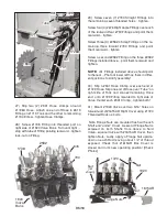
16) Remove the two Flange Bolts securing the
“flange tab” of the “lower left” side of #1610 Front
Grill. In their place, using four 5/16” x 1” long
Flange Bolts and Flange Nuts and four #2005
Washers, mount the #1664 Cylinder Mount...
tighten!
[NOTE:
four #2005 Washers are placed
between “inside face” of #1664A Plate and “out-
side face” of “left” Body Wall. Also for greatest final
“lift height” push #1664A Plate as high as it will go
as you tighten the four Flange Bolts.
]
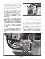
17) Slip five #716 Washers over end of #1664B
Mounting Pin followed by “upper tube” of #2336
Cylinder. Fill out remaining space on Pin with
Washers and secure “end” by “driving in” a #244
Spring Pin.
[NOTE:
Body of Cylinder is “up” and
hydraulic fittings point to the “rear”
]
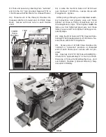
18) Determine number of #716 Washers to fill
space between “outside left face” of Front Hitch
Assembly and “inside face” of Cylinder’s “lower
tube”. Pass #1707 Rod through “outside face” of
Cylinder’s “lower tube”, through the Washers de-
termined above, and then through the 1” hole in
“left face” of Hitch Assembly, coming out the mat-
ing 1” hole on “right face” of Hitch. Center the Rod,
shim out Rod ends with Washers and secure by
“driving in” #244 Spring Pins into each end.
19) Insert #279 Grommet in each 1- 3/4” dia. hole
in #1645 Rear Brace.
[NOTE:
#279 Grommet has
a thinner groove around edge compared to the
1804
1801
1-1/16
”
1664A
1664B
244
2005
716
1610
244
2336
1736
244
1707
716
Hitch
Ass
emb
ly
1694 Outside
Left Face
1737
1664B
54
54


