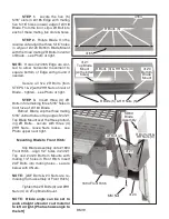
STEP 6.
When both #4107
Locks are fully closed, secure each with
a #1168 Hitch Pin... inset Photo at far
right.
STEP 7.
Your installation of the
#2232 Handle is strictly “operator pref-
erence”. It is installed to the
outside
surface
of the
left wall
of the #4140 Side
Assembly with #AL Bolts and #KK Nuts.
Its orientation and angle should
be adjusted so that the operator can
easily reach and manipulate it... Photos
at right show a typical installation.
STEP 8.
Slip #2209 Grip over
top end
of #2232 Handle.
STEP 9.
See page BM13 for in-
stallation of the #4140 Loop.
Finished assembly and installation of
BM13 Bucket Mouth Kit
BM23
4107
1168
2232
2232
2209
AL Bolt &
KK Nut
4106L
Left
Bracket


