Standard blocks
Block descriptions
ID 441692.01
STÖBER ANTRIEBSTECHNIK
568
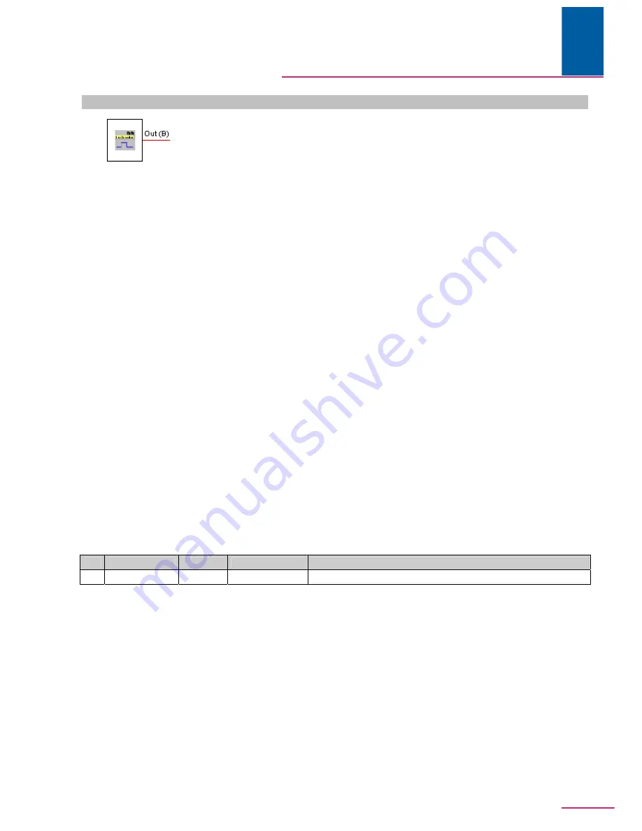
101081 Universal electronic cam
Description
This block implements the functionalities as master cam, slave cam and as cams for the limited and
endless position ranges. The block's behavior is determined by a set of multi-instance parameters:
N140
: Cam enable
N141
: Cam for axis/master; 0: Axis, 1: Master
N142
: Master cam start position (visibility depends on
N141
)
N143
: Master cam end position (visibility depends on
N141
)
N144
: Axis cam start position (visibility depends on
N141
)
N145
: Axis cam end position (visibility depends on
N141
)
N146
: Cam hysteresis master scaling (visibility depends on
N141
)
N147
: Cam hysteresis axis scaling (visibility depends on
N141
)
N148
: Dead time compensation of cam
N149
: Output signal of cam
N150
: Force cam to value
N151
: Dead time compensation limited
N140
to
N151
are multi-instance parameters which are given new parameter coordinates for each
additional block. Predefined coordinates are
N160
-
N171
,
N180
-
N191
,
N200
-
N211
,
N220
-
N231
and
N240
-
N251
. When more than six cams are used, the additional multi-instance parameters are placed
in appropriate coordinates in the Q group.
When
N140
is active, the block indicates whether the drive is within a certain position range (cam). If
the current position is located on or between the start position and the end position, the signal 1 is
output to the output
Out
. The current position is taken from the parameters
I900
/
I901
(slave cam) or
G908
/
G909
(master cam) based on the setting of
N141
.
A hysteresis is specified for the cam block which can be set via
N146
or
N147
. The hysteresis
functions as follows:
The cam block is the state machine. In addition to the
Active
and
Inactive
states, there are four
additional states which determine presence in the hysteresis range. The
Active
or
Inactive
state is
present and it is determined that the cam position requires a change in the output signal but the
position is still within the specified hysteresis range, the state changes to the applicable hysteresis
state, the position of the switching edge is saved, and the output signal is set accordingly. A change
in the output signal is no longer possible in the hysteresis state. A change in the state
Active
or
Inactive
does not occur until the actual position (including dead time compensation) has moved out of
the hysteresis range by the amount of the saved switching edge. A signal change out of this state
becomes possible again.
Outputs
No. Name
Datatype Scaling
Description
1
Out
B
–
Output signal of the cam
Содержание POSIDRIVE MDS 5000
Страница 1: ...from V 5 6 D 02 2012 DE DESCRIPTION 5th generation of STÖBER inverters Blocks ...
Страница 12: ...Organization blocks Block descriptions ID 441692 01 www stoeber de 11 STÖBER ANTRIEBSTECHNIK ...
Страница 22: ...System blocks Block descriptions ID 441692 01 www stoeber de 21 STÖBER ANTRIEBSTECHNIK ...
Страница 322: ...Standard blocks Block descriptions ID 441692 01 www stoeber de 321 STÖBER ANTRIEBSTECHNIK ...
Страница 588: ...Notes Block descriptions ID 441692 01 www stoeber de STÖBER ANTRIEBSTECHNIK ...


