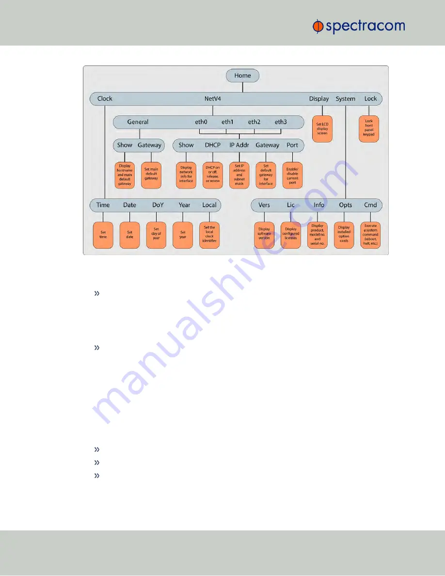
Figure 1-3:
Front panel menu tree
To modify a parameter:
Highlight the menu option and press the ENTER button.
“O” stands for current old setting, and “N” is the new setting.
You can only change the “N” setting.
Use the UP and DOWN arrow keys to scroll through all possible parameter values.
To edit a sequence of numbers:
Use the LEFT and RIGHT arrow keys to select other digits. Once the desired parameter is
displayed, press ENTER to make the new value the current ("O") value. You will be asked
to confirm the setting change. Press ENTER to accept or BACK to cancel the parameter
change.
All entered values are stored in the unit's non- volatile memory and will be restored after a
power cycle.
1.6.4
Status LEDs
Three Status LEDs, located on the unit's front panel, indicate NetClock's current operating status:
POWER
: Green, always on while power is applied to the unit
SYNC
: Tri-color LED indicates the time data accuracy
FAULT
: Two-color, three-state LED, indicating if any alarms are present.
At power up, the unit automatically performs a brief LED test run during which all three LEDs
are temporarily lit.
8
CHAPTER
1
•
NetClock User Reference Guide
Rev.
16
1.6 NetClock 9400 Series Front Panels
Содержание NetClock 9400 Series
Страница 2: ......
Страница 4: ...Blank page II NetClock User Reference Guide...
Страница 16: ...BLANK PAGE XIV NetClock User Reference Guide TABLE OF CONTENTS...
Страница 42: ...BLANK PAGE 1 11 Regulatory Compliance 26 CHAPTER 1 NetClock User Reference Guide Rev 16...
Страница 160: ...BLANK PAGE 2 17 Configuring Outputs 144 CHAPTER 2 NetClock User Reference Guide Rev 16...
Страница 238: ...BLANK PAGE 3 5 Managing the Oscillator 222 CHAPTER 3 NetClock User Reference Guide Rev 16...
Страница 462: ...BLANK PAGE 446 NetClock User Reference Guide...


