Electrical installation
4.9 Other connections
Drive converter cabinet units
82
Operating Instructions, 07/07, A5E00288214A
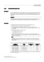
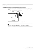
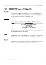
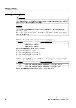
Connecting the braking resistor
WARNING
The cables must only be connected to terminal block -X5 when the cabinet unit is switched
off and the DC link capacitors are discharged.
CAUTION
The braking resistor cables must be laid in such a way that they are short-circuit and
ground-fault proof.
The length of the connecting cables between the cabinet unit and external braking resistor
must not exceed 50 m.
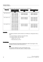
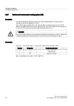
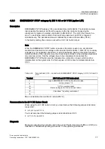
Table 4-31 Terminal block -X5 – connection for external braking resistor
Terminal
Description of function
1
Braking resistor connection
2
Braking resistor connection
Max. connectable cross-section: 70 mm² (AWG 2/0)
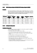
Recommended cable cross-sections:
●
For L61/L64 (25 kW): 35 mm² (AWG 1)
●
For L62/L75 (50 kW): 50 mm² (AWG 1/0)
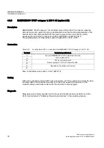
Table 4-32 Installing the thermostatic switch for the external braking resistor in the monitoring train
of the cabinet unit
Terminal
Description of function
T1
Thermostatic switch connection: connection with terminal X541:1 (P24 V)
T2
Thermostatic switch connection: connection with terminal X541:5 (DI11)
Max. connectable cross-section (due to TM31): 1.5 mm² (AWG 14)
Содержание SINAMICS S150
Страница 2: ......
Страница 6: ...Preface Drive converter cabinet units 6 Operating Instructions 07 07 A5E00288214A ...
Страница 14: ...Table of contents Drive converter cabinet units 14 Operating Instructions 07 07 A5E00288214A ...
Страница 28: ...Device overview 2 5 Type plate Drive converter cabinet units 28 Operating Instructions 07 07 A5E00288214A ...
Страница 519: ......
Страница 520: ...Siemens AG Automation and Drives Large Drives P O Box 4743 90025 NÜRNBERG GERMANY www ad siemens com A5E00288214A ...

