Functions, monitoring, and protective functions
9.4 Extended functions
Drive converter cabinet units
370
Operating Instructions, 07/07, A5E00288214A
Stop output cams
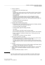
A traversing range can be restricted firstly by software using software limit switches and
secondly the traversing range can be limited by hardware. The function of the stop cams
(hardware limit switches) is used for this purpose. The function of the stop cams is activated
by the 1 signal on the binector input p2568 (activation of stop cams).
Once enabled, the activity of binector inputs p2569 (stop cam, minus) and p2570 (stop cam,
plus) is checked. These are low active cams, i.e. they are active if the 0 signal is present at
binector input p2569 or p2570.
When a stop cam (p2569 or p2570) becomes active, the current motion is stopped using the
maximum delay (p2573) and the corresponding status bit r2684.13 (stop cam active, minus)
or r2684.14 (stop cam active, plus) set.
If the stop cams are approached, only motion away from the stop cam is permitted (if both
stop cams are active, motion cannot be undertaken). Motion away from the stop cam in the
permitted travel direction is detected by the 0/1 edge and the corresponding status bits
(r2684.13 and/or r2684.14) are therefore reset.
Jerk limit
Acceleration and deceleration can change suddenly if jerk limiting has not been activated.
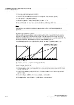
The diagram below shows the traversing profile when jerk limitation has not been activated.
The diagram shows that maximum acceleration (a
max
) and deceleration (d
max
) are effective
immediately. The drive accelerates until the target speed (v
target
) is reached and then
switches to the constant velocity phase.
7LPH
9HORFLW\
$FFHOHUDWLRQ
9H
OR
F
LW
\
P
V
$F
F
HOHUD
WLRQ
P
V
t
Figure 9-23 Jerk limitation deactivated
Jerk limitation can be used to achieve a ramp-like change of both variables, which ensures
"smooth" acceleration and braking as shown in the diagram below. Ideally, acceleration and
deceleration should be linear.
Содержание SINAMICS S150
Страница 2: ......
Страница 6: ...Preface Drive converter cabinet units 6 Operating Instructions 07 07 A5E00288214A ...
Страница 14: ...Table of contents Drive converter cabinet units 14 Operating Instructions 07 07 A5E00288214A ...
Страница 28: ...Device overview 2 5 Type plate Drive converter cabinet units 28 Operating Instructions 07 07 A5E00288214A ...
Страница 519: ......
Страница 520: ...Siemens AG Automation and Drives Large Drives P O Box 4743 90025 NÜRNBERG GERMANY www ad siemens com A5E00288214A ...

