Electrical installation
4.2 Checklist for electrical installation
Drive converter cabinet units
44
Operating Instructions, 07/07, A5E00288214A
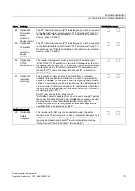
Item Activity
Fulfilled/Complete
17 Option K48
SMC20 Sensor
Module
The SMC20 Sensor Module is used for determining the actual motor
speed and the path length.
The following encoders are supported by the SMC20 Sensor Module:
•
Incremental encoder sin/cos 1Vpp
•
Absolute encoder EnDat
(See "Electrical installation / SMC20 Sensor Module for detecting the
actual motor speed and the path length (option K48)".)
18 Option K50
SMC30 Sensor
Module
The SMC30 Sensor Module is used for determining the actual motor
speed.
The following encoders are supported by the SMC30 Sensor Module:
•
TTL encoder
•
HTL encoder
•
SSI encoder
(See "Electrical installation / SMC30 Sensor Module for detecting the
actual motor speed (option K50)".)
Connecting protection and monitoring devices
19 Option L45
EMERGENCY
STOP
pushbutton
The contacts for the EMERGENCY STOP pushbutton are connected
to terminal -X120 and can be picked off so that they can be integrated
in a higher-level line-side protection concept ("Electrical installation /
EMERGENCY STOP pushbutton (option L45)").
20 Option L57
EMERGENCY
STOP category
0
(230 V AC /
24 V DC)
EMERGENCY STOP category 0 stops the drive in an uncontrolled
manner. No additional wiring is necessary when implemented in
conjunction with option L45.
If the cabinet unit is integrated in an external safety circuit, however,
the contact must be looped in via terminal block -X120 ("Electrical
installation / EMERGENCY STOP category 0; 230 V AC / 24 V DC
(option L57)").
21 Option L59
EMERGENCY
STOP category
1
(230 V AC)
EMERGENCY STOP category 1 stops the drive in a controlled
manner. No additional wiring is necessary when implemented in
conjunction with option L45. If the cabinet unit is integrated in an
external safety circuit, however, the contact must be looped in via
terminal block –X120 (see "Electrical installation / EMERGENCY
STOP category 1; 230 V AC (option L59)").
22 Option L60
EMERGENCY
STOP category
1
(24 V DC)
EMERGENCY STOP category 1 stops the drive in a controlled
manner. No additional wiring is necessary when implemented in
conjunction with option L45. If the cabinet unit is integrated in an
external safety circuit, however, the contact must be looped in via
terminal block –X120 (see "Electrical installation / EMERGENCY
STOP category 1; 24 V DC (option L60)").
23 Option
L61/L62/L64/L6
5
25/50 kW
braking unit
The connecting cables and ground for the braking resistor must be
connected to terminal block –X5: 1/2. A connection must be
established between the braking resistor thermostatic switch and
customer terminal block –A60. When commissioning via AOP30, the
settings for evaluating "external fault 3" must be made. The settings
for evaluating the thermostatic switch as "external fault 2" must be
made (see "Electrical installation / 25 kW Braking unit (option
L61/L64); 50 kW Braking unit (option L62/L65)").
Содержание SINAMICS S150
Страница 2: ......
Страница 6: ...Preface Drive converter cabinet units 6 Operating Instructions 07 07 A5E00288214A ...
Страница 14: ...Table of contents Drive converter cabinet units 14 Operating Instructions 07 07 A5E00288214A ...
Страница 28: ...Device overview 2 5 Type plate Drive converter cabinet units 28 Operating Instructions 07 07 A5E00288214A ...
Страница 519: ......
Страница 520: ...Siemens AG Automation and Drives Large Drives P O Box 4743 90025 NÜRNBERG GERMANY www ad siemens com A5E00288214A ...

