Functions, monitoring, and protective functions
9.3 Drive functions
Drive converter cabinet units
Operating Instructions, 07/07, A5E00288214A
329
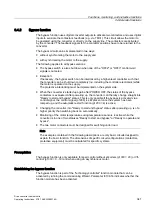
9.3.8.1
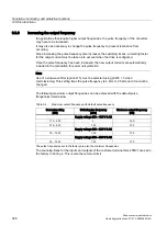
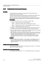
Increasing the pulse frequency
Description
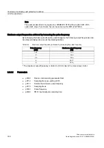
The pulse frequency can be increased in a virtually continuously variable manner to between
the value preassigned in the factory and the maximum pulse frequency which can be set.
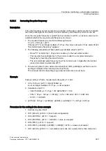
Once the new pulse frequency required has been entered in p0113, a check is carried out to
establish whether the required pulse frequency can be set.
1.
The required frequency is used in the following formula:
X = (0.5 x 1000 µs) / p0113
If the result "X" is an integer multiple of 1.25 µs, the value is accepted. If not, alarm A1224
"Inconsistent pulse frequency" appears.
2.
The following calculation will help obtain a permissible value for p0113:
–
Result "X" is divided by 1.25 µs and rounded up to the next whole number.
–
This result is then multiplied by 1.25 µs and converted to a recommended pulse
frequency by reversing the above formula.
–
The recommended pulse frequency must be rounded up to 3 digits after the decimal
place and entered in parameter p0113.
3.
The scanning time for the customer terminal block TM31 (p4099[x]) must then be set to
an integer multiple of the scanning time of p0115[0].
The minimum limit for the setting range must be taken into account here.
Example
Factory setting: 1.25 kHz, required pulse frequency: 1.3 kHz.
1.
(0.5 x 1000 µs) / p0113 = 384.61538461 µs
is not an integer multiple of 1.25 µs – is not accepted.
2.
Calculation of p0113:
–
384.61538461 µs / 1.25 µs = 307.692307688 => 308
–
308 x 1.25 µs = 385 µs => r0114[1] = (0.5 x 1000 kHz) / 385 = 1.2987 kHz
–
P0113 = 1.299 kHz
3.
p0115[0] = 385 µs => p4099[0] = p4099[1] = p4099[2] = 11 x 385 µs = 4235 µs
Procedure for the setting in the above example
1.
Set drive to pulse inhibit
2.
DO1 (CU320): p0009 = 3 (drive basis configuration)
3.
DO3 (VECTOR): p0112 = 0 (expert)
4.
DO3 (VECTOR): p0113 = 1.299 kHz -> value is accepted
5.
DO4 (TM31): p0112 = 0 (expert)
6.
DO4 (TM31): p4099[0] = p4099[1] = p4099[2] = 4235 -> values are accepted
7.
DO1 (CU320): p0009 = 0 -> calculations are made and a warm start is then carried out.
Содержание SINAMICS S150
Страница 2: ......
Страница 6: ...Preface Drive converter cabinet units 6 Operating Instructions 07 07 A5E00288214A ...
Страница 14: ...Table of contents Drive converter cabinet units 14 Operating Instructions 07 07 A5E00288214A ...
Страница 28: ...Device overview 2 5 Type plate Drive converter cabinet units 28 Operating Instructions 07 07 A5E00288214A ...
Страница 519: ......
Страница 520: ...Siemens AG Automation and Drives Large Drives P O Box 4743 90025 NÜRNBERG GERMANY www ad siemens com A5E00288214A ...

