Electrical installation
4.10 Other connections
Converter cabinet units
Operating Instructions, 07/2016, A5E03347396A
157
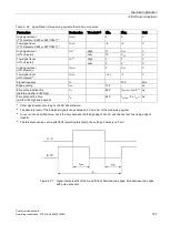
Table 4- 52 Specification of measuring systems that can be connected
Parameters
Designation
Threshold
4)
Min.
Max.
Unit
High signal level
(TTL bipolar at X520 or X521/X531)
1)
U
Hdiff
2
5
V
Low signal level
(TTL bipolar to X520 or X521/X531)
1)
U
Ldiff
-5
-2
V
High signal level
(HTL unipolar)
U
H4)
High
17
V
CC
V
Low
10
V
CC
V
Low signal level
(HTL unipolar)
U
L4)
High
0
7
V
Low
0
2
V
High signal level
(HTL bipolar)
2)
U
Hdiff
3
V
CC
V
Low signal level
(HTL bipolar)
2)
U
Ldiff
-V
CC
-3
V
Signal frequency
f
S
-
300
kHz
Edge spacing
t
min
100
-
ns
Zero pulse inactive time
(before and after A=B=high)
t
Lo
640
(t
ALo-BHi
- t
Hi
)/2
3)
ns
Zero pulse active time
(while A=B=high and beyond)
t
Hi
640
t
ALo-BHi
- 2 x t
Lo 3)
ns
1)
Other signal levels according to the RS 422 standard.
2)
The absolute level of the individual signals varies between 0 V and V
CC
of the measuring system.
3)
t
ALo-BHi
is not a specified value, but is the time between the falling edge of track A and the next but one rising edge of
track B.
4)
The threshold can be set via p0405.04 (switching threshold); the setting on delivery is "Low."
Figure 4-37 Signal characteristic of the A and B track between two edges: time between two edges
with pulse encoders
Содержание SINAMICS G150
Страница 1: ......
Страница 2: ......
Страница 8: ...Foreword Converter cabinet units 8 Operating Instructions 07 2016 A5E03347396A ...
Страница 18: ...Table of contents Converter cabinet units 18 Operating Instructions 07 2016 A5E03347396A ...
Страница 38: ...Device overview 2 5 Type plate Converter cabinet units 38 Operating Instructions 07 2016 A5E03347396A ...
Страница 679: ......
Страница 680: ......

