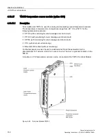
Electrical installation
4.10 Other connections
Converter cabinet units
Operating Instructions, 07/2016, A5E03347396A
151
4.10.17.2
Connecting
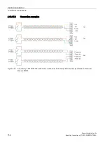
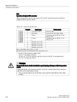
Temperature sensor connections
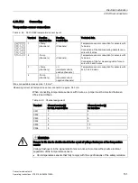
Table 4- 48 X531-X536 temperature sensor inputs
Terminal Function
1x2-/2x2-wire
Function
3 and 4-wire
Technical data
1
+Temp
(channel x)
+
(Channel x)
Temperature sensor connection for sensors with
1x2 wires
Connection of the 2nd measuring cable for sen-
sors with 4 wires
2
-Temp
(channel x)
-
(Channel x)
Temperature sensor connection for sensors with
1x2 wires
Connection of the 1st measuring cable for sen-
sors with 3 and 4 wires.
3
+Temp
(channel y)
+ I
c
(constant current,
positive channel x)
Temperature sensor connection for sensors with
2x2, 3 and 4-wires
4
-Temp
(channel y)
- I
c
(constant current,
negative channel x)
Max. connectable cross-section: 1.5 mm
2
Measuring current via temperature sensor connection: approx. 0.83 mA
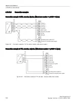
When connecting temperature sensors with 3 wires, a jumper must be inserted between
X53x.2 and X53x.4.
Table 4- 49 Channel assignment
Terminal
Channel number [x]
for 1x2, 3 and 4-wires
Channel number [y]
for 2x2 wires
X531
0
6
X532
1
7
X533
2
8
X534
3
9
X535
4
10
X536
5
11
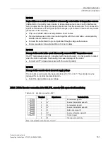
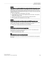
WARNING
Danger to life due to electric shock in the event of voltage flashovers at the temperature
sensor
Voltage flashovers in the signal electronics can occur in motors without safe electrical
separation of the temperature sensors.
•
Use temperature sensors that fully comply with the specifications of the safety isolation.
Содержание SINAMICS G150
Страница 1: ......
Страница 2: ......
Страница 8: ...Foreword Converter cabinet units 8 Operating Instructions 07 2016 A5E03347396A ...
Страница 18: ...Table of contents Converter cabinet units 18 Operating Instructions 07 2016 A5E03347396A ...
Страница 38: ...Device overview 2 5 Type plate Converter cabinet units 38 Operating Instructions 07 2016 A5E03347396A ...
Страница 679: ......
Страница 680: ......

