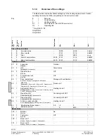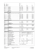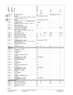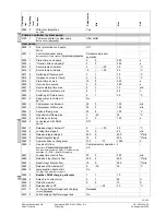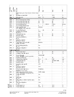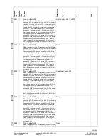
Oper
a
tin
g
line
Oper
a
tin
g
level
Func
tio
n
Defaul
t
val
ue
Min
Max
Unit
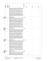
2080 F
With solar integration
No ¦ Yes
Yes
-
Primary controller / system pump
2150 I
Primary controller / system pump
Before buffer ¦ After buffer
After buffer
-
Heat pump
2800 F
Frost protection cond pump
Off ¦ On
Off.
-
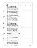
2801 I
Control condenser pump
Automatically ¦ Temp request ¦ Parallel compr operation
Parallel compressor
operation
-
2802 I
Prerun time cond pump
5
0
240
s
2803 I
"Overrun time cond pump"
5
0
240
s
2815 F
Source temp min water
2
−
−
−
/ -20
30
°C
2816 F
Source temp min brine
-5
−
−
−
/ -30
50
°C
2817 F
Switching diff source prot
3
1
10
°C
2818 F
Increase source prot temp
2
0
10
°C
2819 I
Prerun time source
15
0
240
s
2820 I
Overrun time source
5
0
240
s
2821 F
Source startup time max
5
1
10
min
2822 F
Time limit source temp min
4
1
24
h
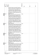
2840 I
Switching diff return temp
4
1
20
°C
2841 F
Keep compr run time min
No ¦ Yes
No
-
2842 I
Compressor run time min
20
0
120
min
2843 I
Compressor off time min
20
0
120
min
2844 F
Switch-off temp max
55
8
100
°C
2845 F
Red switch-off temp max
2
-20
20
°C
2852 F
LP delay on startup
5
0
120
s
2860 F
Lock stage 2 with DHW
Off ¦ On
Off.
-
2861 F
Release stage 2 below OT
5
−
−
−
/ -30
30
°C
2862 F
Locking time stage 2
10
0
40
min
2863 F
Release integral stage 2
250
0
500
°C*min
2864 F
Reset integral stage 2
10
0
500
°C*min
2865 F
Compr sequence changeover
100
−
−
−
/ 10
1000
h
2880 I
Use electric flow
Substitute ¦ Complementary operation HC¦
Complementary operation DHW ¦ Complement ary
operation HC +DHW ¦ End DHW charging
Complementary operation
HC
5
-
2881 I
Locking time electric flow
30
0
255
min
2882 I
Release integr Electric flow
250
0
500
°C*min
2883 I
Reset integr Electric flow
10
0
500
°C*min
2884 I
Release el flow below OT
0
-30
30
°C
2886 F
compensation heat deficit
Off ¦ On ¦ Only with floor curing fct
On.
-
2893 F
Number
:
DHW charging attempts
1
1
10
-
2894 F
Delay 3-ph current error
3
1
40
S
2895 F
Delay flow switch
0
0
10
S
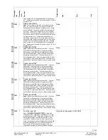
2910 F
Release above OT
- - -
- - - / -30
30
°C
2911 F
For forced buffer storage tank charging
Locked ¦ Released
Released
-
2912 F
Full charging of buffer storage tank
On.
-
6)
6)
6)
53/258
Siemens Switzerland Ltd
User manual RVS61.843, RVS41.813
CE1U2355en_02
HVAC Products
5 Handling
28. September 2009


