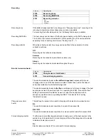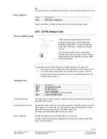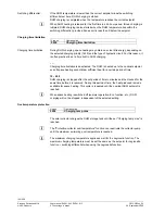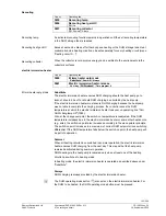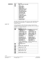
Heat exchanger outside the storage tank and sensor
B36 in the flow (partial plant diagrams 22, 23)
The controller calculates the charging pump’s speed
required to ensure that the charging temperature
acquired by sensor B36 is 2 K above the DHW
setpoint.
235
8A
34
B3
Q3
B31
B36
Q33
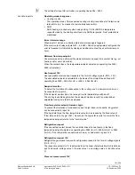
Heat exchanger outside the storage tank, with
primary controller.
The controller calculates the charging pump’s speed
required to ensure that the charging temperature
acquired by sensor B35 is 2 K above the DHW
setpoint. In this case, primary controller sensor B35
must be located in the intermediate circuit.
If B36 is connected as well, B35 must be positioned
as the primary controller sensor. In this case, the
controller calculates the speed required to ensure that
the DHW se charging increase acquired by
sensor B35 is achieved.
23
58
A
3
4
B3
Q3
B31
B36
Q33
B35
Speed control of intermediate circuit pump Q33
The controller calculates the speed of the intermediate circuit pump required to ensure
that the return temperature acquired by sensor B36 is 2 K above the DHW setpoint.
If no B36 is connected, sensor B35 is used to make the calculation.
If no valid sensor is connected, the pump will not be speed-controlled.
166/258
Siemens Switzerland Ltd
User manual RVS61.843, RVS41.813
CE1U2355en_02
HVAC Products
6 The settings in detail
28. September 2009


