5.1.4
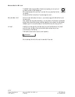
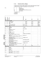
Overview of the settings
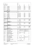
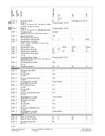
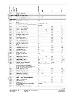
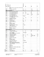
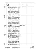
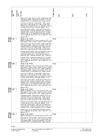
The table below shows all available settings up to the heating engineer level. Certain
operating lines may be hidden, depending on the unit version used.
E
=
End-user
I
=
Commissioning
F
=
Heating engineer
ST
=
Can only be set via ACS700 service tool
OL
=
Operating line
1)
Only QAA75../78..
Only RVS41..
Only RVS61..
Oper
a
tin
g
line
Oper
a
tin
g
level
Func
tio
n
Defaul
t
val
ue
Min
Max
Unit
Time of day and date
1
E
Hours/minutes
-
00:00
23:59
hh:mm
2
E
Day / month
-
01.01
31.12
dd.MM
3
E
Year
-
2004
2099
yyyy
5
F
Start of summertime
25.03 01.01
31.12
dd.MM
6
F
End of summertime
25.10 01.01
31.12
dd.MM
Operator section
20
E
Language
German ¦ …
German
-
22
F
Info
Temporarily ¦ Permanently
Temporarily
-
26
F
Operation lock
Aus ¦ Ein
Off.
-
27
F
Programming lock
Aus ¦ Ein
Off.
-
28
I
Direct adjustment
Automatic storage ¦ Storage with confirmation
Storage with confirmation
40
I
Used as
Room unit 1 ¦ Room unit 2 ¦ Room unit P ¦ Operator unit 1 ¦
Operator unit 2 ¦ Operator unit P ¦ Service unit
Room unit 1
-
42
I
Assignment device 1
Heating circuit 1 ¦ Heating circuits 1 and 2 ¦ Heating circuits
1 and P ¦ All heating circuits
Heating circuit 1
-
44
I
Operation HC2
Commonly with HC1 ¦ Independently
Commonly with HC1
-
46
I
Operation HCP
Commonly with HC1 ¦ Independently
Commonly with HC1
-
48
I
Action occupancy button
None ¦ Heating circuit 1 ¦ Heating circuit 2 ¦ Commonly
Heating circuit 1
-
54
F
Readjustment room sensor
0.0
-3
3
°C
70
F
Software version
-
0
99.9
-
Radio links
120
I
Binding
No ¦ Yes
No
-
121
I
Test mode
Aus ¦ Ein
Off.
-
130
I
Room unit 1
Missing ¦ Ready ¦ No recept’n ¦ Change batt
-
-
131
I
Room unit 2
Missing ¦ Ready ¦ No recept’n ¦ Change batt
-
-
Key
1)
1)
46/258
Siemens Switzerland Ltd
User manual RVS61.843, RVS41.813
CE1U2355en_02
HVAC Products
5 Handling
28. September 2009

