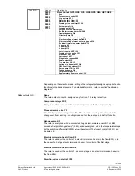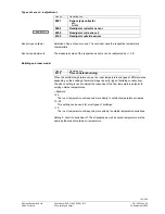
Extension module
Line no.
Operating line
6020
6021
Function extension modules 1 and 2
None
Multifunctional
Cooling circuit 1
Heating circuit 2
Solar DHW
Primary controller / system pump
DHW primary controller
Instantaneous DHW heater
Connection terminal on module
QX21
QX22
QX23
BX21
BX22
H2
Multifunctional
*
*
*
*
*
*
Cooling circuit 1
Y23
Y24
Q24
B16
*
*
Heating circuit 2
Y5
Y6
Q6
B12
*
*
Solar DHW
*
*
Q5
B6
B31
*
Primary controller / system
pump
Y19
Y20
Q14
B15
*
*
DHW primary controller
Y31
Y32
Q3
B35
*
*
Instantaneous DHW heater
Y33
Y34
Q34
B38
B39
F
S
* Freely selectable in Q…/ BX...
FS = flow switch
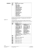
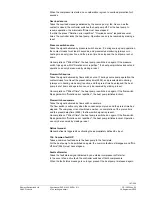
Multifunctional
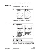
Functions that can be assigned to the multifunctional inputs / outputs appear on
operating lines 6030, 6031, 6032 and 6040, 6041.
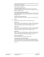
Cooling circuit 1
For this application, the respective settings of menu "Cooling circuit 1" can be adapted.
Heating circuit 2
For this application, the respective settings of menu "Heating circuit 2" can be adapted.
Solar DHW
For this application, the respective settings of menu "Solar" can be adapted.
Primary controller / system pump
For this application, the respective settings of menu "Primary controller / system pump"
can be adapted.
DHW primary controller
For this application, the respective settings of menu "DHW storage tank" can be
adapted.
Instantaneous DHW heater
For this application, the respective settings of menu "Instantaneous DHW heater" can
be adapted.
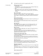
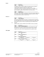
Frost protection on the extension module
Heating circuit
Frost protection for the heating circuit on the extension module operates the same way
as frost protection for the heating circuit connected to the controller (see page 97).
Frost protection for the plant (see page 194) also acts on the heating circuit of the
extension module.
189/258
Siemens Switzerland Ltd
User manual RVS61.843, RVS41.813
CE1U2355en_02
HVAC Products
6 The settings in detail
28. September 2009

