background image

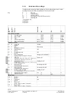
Oper

a

tin

line 

Oper

a

tin

level 

Func

tio

Defaul

val

ue 

Min 

Max 

Unit 

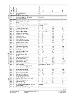
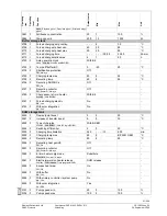
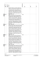
5891  I 

Relay output QX2 

None ¦ Compressor 2 K2 ¦ Process revers valve Y22 ¦ Hot-
gas temp K31 ¦ El imm heater 1 flow K25 ¦ El imm heater 2 
flow K26 ¦ Div valve cool source Y28 ¦ System pump Q14 ¦ 
Cascade pump Q25 ¦ Heat gen shutoff valve Y4 ¦ El imm 
heater DHW K6 ¦ Circulating pump Q4 ¦ St tank transfer 
pump Q11 ¦ DHW intern circ pump Q33 ¦ DHW mixing 
pump Q35 ¦ Collector pump Q5 ¦ Collector pump 2 Q16 ¦ 
Solar pump ext exch K9 ¦ Solar ctrl elem buffer K8 ¦ Solar 
ctrl elem swi pool K18 ¦ El imm heater buffer K16 ¦ H1 
pump Q15 ¦ H2 pump Q18 ¦ H3 pump Q19 ¦ Heat circuit 
pump HCP Q20 ¦ 2nd pump speed HC1 Q21 ¦ 2nd pump 
speed HC2 Q22 ¦ 2nd pump speed HCP Q23 ¦ Diverting 
valve cooling Y21 ¦ Air dehumidifier K29 ¦ Heat request 
K27 ¦ Refrigeration request K28 ¦ Alarm output K10 ¦ Time 
program 5 K13 

Source pump Q8 / fan K19   

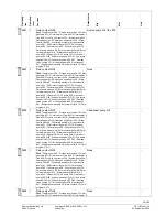
5891  I 

Relay output QX2 

None ¦ Compressor 2 K2 ¦ Process revers valve Y22 ¦ Hot-
gas temp K31 ¦ El imm heater 1 flow K25 ¦ El imm heater 2 
flow K26 ¦ Div valve cool source Y28 ¦ System pump Q14 ¦ 
Cascade pump Q25 ¦ Heat gen shutoff valve Y4 ¦ El imm 
heater DHW K6 ¦ Circulating pump Q4 ¦ St tank transfer 
pump Q11 ¦ DHW intern circ pump Q33 ¦ DHW mixing 
pump Q35 ¦ Collector pump Q5 ¦ Collector pump 2 Q16 ¦ 
Solar pump ext exch K9 ¦ Solar ctrl elem buffer K8 ¦ Solar 
ctrl elem swi pool K18 ¦ El imm heater buffer K16 ¦ H1 
pump Q15 ¦ H2 pump Q18 ¦ H3 pump Q19 ¦ Heat circuit 
pump HCP Q20 ¦ 2nd pump speed HC1 Q21 ¦ 2nd pump 
speed HC2 Q22 ¦ 2nd pump speed HCP Q23 ¦ Diverting 
valve cooling Y21 ¦ Air dehumidifier K29 ¦ Heat request 
K27 ¦ Refrigeration request K28 ¦ Alarm output K10 ¦ Time 
program 5 K13  

None 


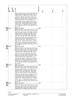
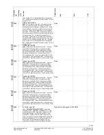
5892  I 

Relay output QX3 

None ¦ Compressor 2 K2 ¦ Process revers valve Y22 ¦ Hot-
gas temp K31 ¦ El imm heater 1 flow K25 ¦ El imm heater 2 
flow K26 ¦ Div valve cool source Y28 ¦ System pump Q14 ¦ 
Cascade pump Q25 ¦ Heat gen shutoff valve Y4 ¦ El imm 
heater DHW K6 ¦ Circulating pump Q4 ¦ St tank transfer 
pump Q11 ¦ DHW intern circ pump Q33 ¦ DHW mixing 
pump Q35 ¦ Collector pump Q5 ¦ Collector pump 2 Q16 ¦ 
Solar pump ext exch K9 ¦ Solar ctrl elem buffer K8 ¦ Solar 
ctrl elem swi pool K18 ¦ El imm heater buffer K16 ¦ H1 
pump Q15 ¦ H2 pump Q18 ¦ H3 pump Q19 ¦ Heat circuit 
pump HCP Q20 ¦ 2nd pump speed HC1 Q21 ¦ 2nd pump 
speed HC2 Q22 ¦ 2nd pump speed HCP Q23 ¦ Diverting 
valve cooling Y21 ¦ Air dehumidifier K29 ¦ Heat request 
K27 ¦ Refrigeration request K28 ¦ Alarm output K10 ¦ Time 
program 5 K13 

Condenser pump Q9 


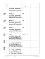
5892  I 

Relay output QX3 

None ¦ Compressor 2 K2 ¦ Process revers valve Y22 ¦ Hot-
gas temp K31 ¦ El imm heater 1 flow K25 ¦ El imm heater 2 
flow K26 ¦ Div valve cool source Y28 ¦ System pump Q14 ¦ 
Cascade pump Q25 ¦ Heat gen shutoff valve Y4 ¦ El imm 
heater DHW K6 ¦ Circulating pump Q4 ¦ St tank transfer 
pump Q11 ¦ DHW intern circ pump Q33 ¦ DHW mixing 
pump Q35 ¦ Collector pump Q5 ¦ Collector pump 2 Q16 ¦ 
Solar pump ext exch K9 ¦ Solar ctrl elem buffer K8 ¦ Solar 
ctrl elem swi pool K18 ¦ El imm heater buffer K16 ¦ H1 
pump Q15 ¦ H2 pump Q18 ¦ H3 pump Q19 ¦ Heat circuit 
pump HCP Q20 ¦ 2nd pump speed HC1 Q21 ¦ 2nd pump 
speed HC2 Q22 ¦ 2nd pump speed HCP Q23 ¦ Diverting 
valve cooling Y21 ¦ Air dehumidifier K29 ¦ Heat request 
K27 ¦ Refrigeration request K28 ¦ Alarm output K10 ¦ Time 
program 5 K13  

None 


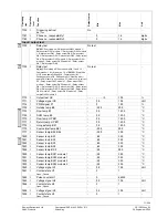
5894  I 

Relay output QX4 

None ¦ Compressor 2 K2 ¦ Process revers valve Y22 ¦ Hot-
gas temp K31 ¦ El imm heater 1 flow K25 ¦ El imm heater 2 

None 


4)


6)


4)


6)


4)


59/258 

Siemens Switzerland Ltd 

User manual RVS61.843, RVS41.813 

CE1U2355en_02 

HVAC Products 

5 Handling 

28. September 2009 

Содержание Albatros2 RVA78.690

Страница 1: ...Albatros2 Heat pump controller User manual RVS41 813 RVS61 843 AVS75 AVS37 QAA75 QAA78 QAA55 Edition 2 1 Controller series B CE1U2355en_02 28 September 2009 Siemens Switzerland Ltd HVAC Products ...

Страница 2: ...2 258 Siemens Switzerland Ltd User manual RVS61 843 RVS41 813 CE1U2355en_02 HVAC Products 28 September 2009 ID A6V10084543 doc ID A6V10084545 pdf ...

Страница 3: ...S75 390 21 Terminal markings 22 Assignment of terminals 22 3 4 Operator unit AVS37 294 23 Mounting method 23 3 5 Operator unit AVS37 390 24 Connections 24 Dimensions 24 3 6 Room unit QAA55 25 Engineering 25 Dimensions and drilling plan 25 3 7 Room unit QAA75 26 Engineering 26 Dimensions and drilling plan 27 3 8 RF components 28 3 8 1 RF module AVS71 390 28 3 8 2 Room unit QAA78 610 29 Engineering ...

Страница 4: ...etting principle 43 Example Setting the time of day 43 5 1 3 User levels 44 Setting structure End user 45 Setting structure Heating engineer 45 5 1 4 Overview of the settings 46 5 2 QAA55 77 5 2 1 Operation 77 Operating elements 77 Display choices 77 Selecting pace heating mode 77 Indication of cooling mode 78 Adjusting the room temperature setpoint 78 Occupancy button 78 5 2 2 Programming 79 6 Th...

Страница 5: ...t 1 97 Operating mode 98 Setpoints 98 Release 98 Cooling curve 99 ECO 99 Summer compensation 100 Flow temperature setpoint limits 100 Room influence 101 Room temperature limitation 102 Mixing valve control 102 Dewpoint monitoring 103 Buffer storage tank primary controller 104 Remote control 104 Frost protection for the heating circuit 105 6 8 Domestic hot water 105 Overview 105 Setpoints 105 Relea...

Страница 6: ...y counter electricity natural gas 143 Counter performance factor 144 Fixed day storage yearly performance factor 145 6 14 Cascade 148 Control 148 Heat source sequence 148 Electric immersion heaters in the cascade 149 6 15 Supplementary source only RVS41 150 Operating mode 150 Overtemperature protection 150 Control 150 6 16 Solar 152 Overview 152 Charging controller dT 152 Priority 153 Start functi...

Страница 7: ...mp 172 Solar 173 Buffer storage tank 174 Output relay QX 174 Function output QX4 Mod 179 Sensor input BX1 BX2 BX3 BX4 BX5 179 Input H1 H3 180 Input EX1 EX2 EX3 EX4 EX5 EX6 EX7 186 Mixing group 188 Extension module 189 Frost protection on the extension module 189 QX extension module 190 BX extension module 191 H2 extension module 191 10V output UX 192 Types of sensor readjustment 193 Building and r...

Страница 8: ...gnostics consumers 221 Outside temperature 221 Room 221 Heating circuits 1 2 P 222 Cooling circuit 1 222 Domestic hot water 223 Swimming pool 223 Primary controller 223 Common flow 223 Buffer storage tank 223 Input H1 224 Water pressure 224 States multifunctional relays 224 States of relays extension modules 1 and 2 224 6 29 Pump kick 225 7 Plant diagrams 226 7 1 Basic diagrams 226 Legend catalog ...

Страница 9: ...Switzerland Ltd User manual RVS61 843 RVS41 813 CE1U2355en_02 HVAC Products Contents 28 September 2009 8 6 RF repeater AVS14 390 247 8 7 Sensor characteristics 248 8 7 1 NTC 1k 248 8 7 2 NTC 10k 249 8 7 3 Pt1000 249 ...

Страница 10: ...om unit wireless QAA55 110 Room unit RDX33 21 RDX43 2 Room thermostat with LCD to release heat pump AVS38 291 Dummy cover 96 x 144 mm AVS71 390 RF module AVS14 390 RF repeater AVS13 399 Outside sensor with RF module AVS82 490 Ribbon cable for extension module AVS82 491 Ribbon cable for operator unit The following training demonstration cases are available KF8921 Demo case for RVS61 843 KF8920 Demo...

Страница 11: ... Process Bus Basic Unit RVS LPB Wired Remote Service Tool Mobile SMS Pager Fax WEB Telephone Network Telephone SMS OCI611 OCI700 RF module ACS700 BSB Boiler System Bus Room Unit RF Repeater RF Toutside BSB RF Service Unit RU HMI RU wireless wireless wireless Basic Unit RVSxx Extension mod AVS75 max 2 BSB W LPB Local Process Bus Basic Unit RVS LPB Wireless 11 258 Siemens Switzerland Ltd User manual...

Страница 12: ...l room unit C E D A 2359Z02 T C D F A E 2359Z04 T Operation with cleartext operator unit optionally with additional room unit A Basic unit RVS C Room unit QAA75 78 QAA55 D Outside sensor AVS13 E Operator unit AVS37 294 clear text E1 Operator unit AVS37 390 basic F RF module AVS71 12 258 Siemens Switzerland Ltd User manual RVS61 843 RVS41 813 CE1U2355en_02 HVAC Products 1 Overview 28 September 2009...

Страница 13: ...n using the products all requirements specified in the chapters on Handling and Technical data must be satisfied Local regulations for installation etc must be complied with Do not open the units If not observed warranty becomes void 13 258 Siemens Switzerland Ltd User manual RVS61 843 RVS41 813 CE1U2355en_02 HVAC Products 2 Safety notes 28 September 2009 ...
Страница 14: ...e accessible and no objects should be placed there If the controller is enclosed in another insulating casing a clearance of up to 100 mm must be observed around the cooling slots The controller is designed conforming to the directives for safety class II devices mounted in compliance with these regulations Power to the controller may only be supplied when completely fitted If this is not observed...

Страница 15: ...unting and installation 28 September 2009 2359Z10 x Dimensions and drilling plan L B L1 B1 2358M01 L B H L1 B1 RVS61 843 281 121 52 270 110 RVS41 813 181 121 52 170 110 Dimension X Connectors with tongues minimum 70 mm Connector without tongues minimum 60 mm Total height required Dimensions in mm ...

Страница 16: ... EX7 EX6 EX5 EX4 EX3 EX2 EX1 E10 E9 N L 2355Z02 M UX M BX5 M BX4 M BX3 M BX2 M BX1 M M B91 M B71 M B1 M B21 M B9 M B3 M B81 H3 M H1 G CL CL CL CL CL CL MB DB B84 B92 Terminal markings RVS41 813 Use Terminal Connector type L Mains connection live AC 230 V Mains connection protective earth N Mains connection neutral conductor L N AGP4S 03E 109 E9 Low pressure E10 High pressure K AGP4S 02J 109 EX1 Mu...

Страница 17: ...B 109 N Neutral conductor Protective earth Q8 K19 Source pump Fan U AGP8S 03C 109 N Neutral conductor Protective earth Q9 Condenser pump V AGP8S 03D 109 QX1 1 Multifunctional output N Neutral conductor Protective earth QX2 2 Multifunctional output W AGP8S 04E 109 N Neutral conductor Protective earth QX3 3 Multifunctional output X AGP8S 03E 109 N Neutral conductor Protective earth QX4 4 Multifuncti...

Страница 18: ... sensor M Ground k AGP4S 02D 109 B21 Flow temperature sensor heat pump M Ground n AGP4S 02F 109 B1 Flow temperature sensor HC1 M Ground p AGP4S 02G 109 B71 Return temperature sensor heat pump M Ground q AGP4S 02K 109 B91 Source inlet temperature M Ground r AGP4S 02L 109 B84 B92 Evaporator temperature sensor Source outlet temperature sensor M Ground s AGP4S 02S 109 BX1 Multifunctional sensor input ...

Страница 19: ... N AGP4S 03E 109 EX1 Multifunctional input EX1 EX2 Multifunctional input EX2 EX3 Multifunctional input EX3 EX4 Multifunctional input EX4 EX5 Multifunctional input EX5 EX6 Multifunctional input EX6 EX7 Multifunctional input EX7 E AGP4S 07A 109 N Neutral conductor Protective earth QX1 Multifunctional output R AGP8S 03A 109 N Neutral conductor Protective earth QX2 Multifunctional output U AGP8S 03C 1...

Страница 20: ...Operator unit HMI X30 AVS82 491 109 cable DB LPB data bus MB LPB ground bus a AGP4S 02H 109 CL BSB data bus CL BSB ground bus b AGP4S 02A 109 CL Data bus room unit 1 CL Ground bus room unit 1 G Power supply optional lighting b AGP4S 03D 109 H1 Digital DC 0 10 V input H1 M Ground H3 Digital DC 0 10 V input H3 e AGP4S 03G 109 UX Multifunctional analog output M Ground z AGP4S 02U 109 BX1 Multifunctio...

Страница 21: ...odule must be connected to terminal X50 of the basic unit using the AVS83 490 109 connecting cable The connectors are coded Connections 3 3 1 Connection terminals AVS75 390 S T N L QX23 N QX22 N QX21 N L 050110A 000020 AVS75 390 109 1PAVS75 390 109 S050110000020 2359Z49 1 1 2 module 2 2 1 2 module 1 M H2 M BX22 M BX21 X30 n n n 21 258 Siemens Switzerland Ltd User manual RVS61 843 RVS41 813 CE1U235...

Страница 22: ...age Use Space Connector type Operator unit X30 AVS82 491 109 BX21 Assignment according to function AGP4S 02F 109 M Ground n BX22 Assignment according to function AGP4S 02F 109 M Ground n H2 Digital 0 10 V input AGP4S 02F 109 M Ground n Low voltage Assignment of terminals The 2 parameters Function extension module 1 operating line 6020 Function extension module 2 6021 are used to define usage of th...

Страница 23: ...nnected to terminal X30 of the basic unit using the AVS82 491 109 connecting cable The connectors are coded 2358M03 144 96 90 27 42 4 17 Dimensions 144 0 5 3 0 92 0 8 0 138 1 0 2358M05 96 Panel cutout 23 258 Siemens Switzerland Ltd User manual RVS61 843 RVS41 813 CE1U2355en_02 HVAC Products 3 Mounting and installation 28 September 2009 ...
Страница 24: ... the AVS82 491 109 connecting cable The connectors are coded Dimensions 2354M01 13 0 5 A A Control panel front The AVS37 390 operator unit is a PCB version without casing supplied by Siemens 24 258 Siemens Switzerland Ltd User manual RVS61 843 RVS41 813 CE1U2355en_02 HVAC Products 3 Mounting and installation 28 September 2009 ...
Страница 25: ...ters above the floor In the case of wall mounting there must be sufficient clearance above the unit enabling it to be fitted and removed When the unit is removed from its base power is cut off so that the unit is out of operation 2284Z33a 2284Z34a 2284Z35a Mounting The controller must not be exposed to dripping water 1 3 4 5 6 2 2284Z40 Connections 1 CL BSB data 2 CL BSB ground Dimensions and dril...

Страница 26: ...rces about 1 5 meters above the floor In the case of wall mounting there must be sufficient clearance above the unit enabling it to be fitted and removed When the unit is removed from its base power is cut off so that the unit is out of operation Mounting method 2359Z21 2359Z25 2359Z20 2359Z26 2359Z24 Connections Terminal Designation QAA75 610 QAA75 611 1 CL BSB data BSB data 2 CL BSB ground BSB g...

Страница 27: ...and drilling plan 42 185 2359Z12 100 82 2359Z50 4 2 9 56 60 100 80 11 39 67 27 258 Siemens Switzerland Ltd User manual RVS61 843 RVS41 813 CE1U2355en_02 HVAC Products 3 Mounting and installation 28 September 2009 ...

Страница 28: ...cing wireless communication With this type of device the system components such as room units transmit data with no need for laying cables Engineering Do not install the RF module inside metal casings e g inside the heat pump 2359Z23 Mounting method 2359Z57 A B LED Button Connection The prefabricated cable is to be connected to terminal X60 of the controller Prior to connecting the module the basi...

Страница 29: ...urately as possible without getting adversely affected by direct solar radiation or other heat or refrigeration sources about 1 5 meters above the floor In the case of wall mounting there must be sufficient clearance above the unit enabling it to be fitted and removed Mounting with the base 2359Z26 2359Z25 2359Z20 2359Z21 2359Z22 29 258 Siemens Switzerland Ltd User manual RVS61 843 RVS41 813 CE1U2...

Страница 30: ...ke the appropriate selection Then press the OK button 6 Set the setting knob to YES and press the OK button The process of opening the connection is started 7 The display shows the progress of opening the connection in This process can take 2 to 120 seconds 8 The connection is established when Device ready appears and the LED on the RF module extinguishes The test is made to check the quality of t...

Страница 31: ...ther mounting location should be chosen or the AVS14 390 RF repeater should be used Dimensions and drilling plan 42 185 2359Z12 100 82 2359Z50 4 2 9 56 60 100 80 11 39 67 31 258 Siemens Switzerland Ltd User manual RVS61 843 RVS41 813 CE1U2355en_02 HVAC Products 3 Mounting and installation 28 September 2009 ...

Страница 32: ...he radio transmitter s mounting location should be chosen such that batteries can be easily changed Mounting method RF transmitter Outside sensor The outside sensor is to be connected to the radio transmitter via a 2 core cable the connections are interchangeable The device is powered by two 1 5 V alkaline batteries type AAA LR03 Connections 2359Z54 2359Z30 2359Z33 2359Z59 2359Z31 2359Z55 AAA AAA ...

Страница 33: ...nection is established when the LED on the RF module extinguishes 4 Press the button on the transmitter of the wireless outside sensor briefly again until the LED extinguishes The test is made to check the quality of the radio link The test can be aborted by pressing the ESC button While the radio link can be opened on the controller the test should be made at the location where the room unit will...

Страница 34: ...le starts blinking at high frequency Establishment 2359Z56 Button LED 2 Press the button on the installed radio repeater until the LED start flashing at high frequency 3 The connection is established when the LED on the RF module extinguishes The test is made to check the quality of the radio link Testing The test can be aborted by pressing the ESC button While the radio link can be opened on the ...

Страница 35: ...s to the required system components are operational consult menus 130 through 135 on menu Wireless operating level Commissioning 35 258 Siemens Switzerland Ltd User manual RVS61 843 RVS41 813 CE1U2355en_02 HVAC Products 3 Mounting and installation 28 September 2009 ...

Страница 36: ...tics of consumers operating line Outside temp attenuated 8703 Function check To facilitate commissioning and fault tracing the controller can be used to make input and output tests With these tests the controller s inputs and outputs can be checked To make the tests switch to menu Input output test and go through all available setting lines If faults occurred during the tests please refer to the d...

Страница 37: ...nd settings Occupancy button Cooling button Displaying information Selection of DHW heating Selection of space Operator unit AVS37 Information display Adopting the setting Quitting the setting Service socket BSB Cooling button HP reset and defrost button Adjustment of Comfort setpoint Navigation and settings 37 258 Siemens Switzerland Ltd User manual RVS61 843 RVS41 813 CE1U2355en_02 HVAC Products...

Страница 38: ... mode the room temperature is controlled in accordance with the time program Characteristics of automatic mode Heating mode according to the time program Temperature setpoints per heating program Comfort setpoint or Reduced setpoint Protective functions active Automatic summer winter changeover and automatic 24 hour heating limit active ECO functions Continuous operation or Continuous operation ma...

Страница 39: ...ance with the time program Temperature setpoint in accordance with Comfort setpoint cooling Protective functions active Cooling limit depending on the outside temperature Selecting DHW heating mode The button is used to switch DHW heating mode on and off The selection made is indicated by a bar which appears below the respective symbol DHW heating mode On The DHW is heated according to the selecte...

Страница 40: ...ng energy changeover from Comfort setpoint to OFF When the rooms are occupied again press again the occupancy button to return to normal heating changeover from Reduced to Comfort setpoint or to cooling changeover from OFF to Comfort setpoint In heating mode In cooling mode Heating to the Comfort setpoint Cooling to the Comfort setpoint Heating to Reduced setpoint Cooling off no symbol The occupan...

Страница 41: ...n stage 1 off time min Remain stage 2 off time min Remain stage 1 on time min Remain stage 2 on time min Exception In exceptional cases the basic display shows one of the following symbols Error messages If this symbol appears an error in the plant has occurred Press the info button and read further information Text3 Text4 0 4 8 12 16 20 24 AUTO 2359Z140 30 Flowsensor 1 Error Service or special op...

Страница 42: ...frosting or on completion of the maximum permissible defrost time and permitted number of defrost attempts the heat pump is automatically released again For more information on the defrost function refer to page 130 ff HP reset Pending error messages from the heat pump are reset with this button The preset switch on delay is bridged thus avoiding undesirable waiting times during commissioning or f...

Страница 43: ...1 0 4 8 12 16 20 24 AUTO 2359Z140 Roomtemperature Basic display If the basic display is not shown press the ESC button to go back Press OK 2 Text3 0 4 8 12 16 20 24 AUTO 2359Z140 Operator section Time of dayanddate The bottom section of the display shows various menus Turn the setting knob until menu Time of day and date appears Press the OK button to confirm 3 0 4 8 12 16 20 24 AUTO 2359Z140 Time...

Страница 44: ...ircuit 1 Time program heating circuit 2 Time program heating circuit P Holidays heating circuit 1 Diagnosticsof consumers Hours minutes Month day Year Start of summer time End of summer time Hours 1 24 h Minutes 0 60 min 5 1 3 User levels The user levels only allow authorized user groups to make settings To reach the Operation Display example Description required user level proceed as follows 1 0 ...

Страница 45: ... highlighted On 2359Z139 OEM Heating engineer Commissioning Enduser Time of day and date Operator section Time program heatingcircuit P Holidays heating circuit 1 Diagnosticsof consumers Hours minutes Month day Hours 1 24 h Minutes 0 60 min Setting structure Heating engineer Wireless Time program heatingcircuit 1 Time program heatingcircuit 2 Year Start of summer time End of summer time Time of da...

Страница 46: ...ff 28 I Direct adjustment Automatic storage Storage with confirmation Storage with confirmation 40 I Used as Room unit 1 Room unit 2 Room unit P Operator unit 1 Operator unit 2 Operator unit P Service unit Room unit 1 42 I Assignment device 1 Heating circuit 1 Heating circuits 1 and 2 Heating circuits 1 and P All heating circuits Heating circuit 1 44 I Operation HC2 Commonly with HC1 Independently...

Страница 47: ... 00 00 24 00 hh mm 516 E Default values No Yes No 1 Time prog heating circuit 2 520 E Preselection Mo Su Mo Fr Sa Su Mo Tu We Th Fr Sa Su Mo Su 521 E 1 Phase on 06 00 00 00 24 00 hh mm 522 E 1 Phase off 22 00 00 00 24 00 hh mm 523 E 2 Phase on 24 00 00 00 24 00 hh mm 524 E 2 Phase off 24 00 00 00 24 00 hh mm 525 E 3 Phase on 24 00 00 00 24 00 hh mm 526 E 3 Phase off 24 00 00 00 24 00 hh mm 536 E D...

Страница 48: ...ing level Frost protection Reduced Frost protection Holidays heating circuit P 662 E Start 01 01 31 12 dd MM 663 E End 01 01 31 12 dd MM 668 E Operating level Frost protection Reduced Frost protection Heating circuit 1 710 E Comfort cooling setpoint 20 0 Operating line 712 Operating line 716 C 712 E Reduced setpoint 19 Operating line 714 Operating line 710 C 714 E Frost protection setpoint 10 0 4 ...

Страница 49: ...g mode changeover None Protection Reduced Comfort Automatic Protection Cooling circuit 1 901 E Operating mode Off Automatic Automatically 902 E Comfort cooling setpoint 24 15 40 C 907 E Release 24h day Time progr HC Time program 5 24h day 908 I Flow temp setp at OT 25 C 20 6 35 C 909 I Flow temp setp at OT 35 C 16 6 35 C 912 I Cooling limit at OT 20 8 35 C 913 F Lock time after end of heating 24 8...

Страница 50: ...050 F Room influence 20 1 100 1060 F Room temperature limitation 1 0 5 4 C 1070 F Boost heating 5 0 20 C 1080 F Quick setback Off Down to reduced setpoint Down to frost prot setpoint Down to reduced setpoint 1090 F Optimum start control max 0 00 00 00 00 00 00 06 00 h min s 1091 F Optimum top control max 0 00 00 00 00 00 00 06 00 h min s 1100 F Reduced setpoint increase start 30 10 C 1101 F Reduce...

Страница 51: ...mperature limitation 1 0 5 4 C 1370 F Boost heating 0 20 C 1380 F Quick setback Off Down to reduced setpoint Down to frost prot setpoint Down to reduced setpoint 1390 F Optimum start control max 0 00 00 00 00 00 00 06 00 h min s 1391 F Optimum top control max 0 00 00 00 00 00 00 06 00 h min s 1400 F Reduced setpoint increase start 30 10 C 1401 F Reduced setpoint increase end 15 30 Operating line 1...

Страница 52: ...ase Time program 3 HCP DHW release Time program 4 DHW Time program 5 Time program 3 HCP 1661 F Circulating pump cycling Off On Off 1663 F Circulation setpoint 45 8 80 C Pump Hx 2010 F H1 Excess heat draw Off On On 2012 F H1 with buffer No Yes Yes 2014 F H1 prim contr system pump No Yes Yes 2015 F H1 Refrigeration request 2 pipe system 4 pipe system 2 pipe system 2035 F H2 Excess heat draw Off On O...

Страница 53: ...p max 55 8 100 C 2845 F Red switch off temp max 2 20 20 C 2852 F LP delay on startup 5 0 120 s 2860 F Lock stage 2 with DHW Off On Off 2861 F Release stage 2 below OT 5 30 30 C 2862 F Locking time stage 2 10 0 40 min 2863 F Release integral stage 2 250 0 500 C min 2864 F Reset integral stage 2 10 0 500 C min 2865 F Compr sequence changeover 100 10 1000 h 2880 I Use electric flow Substitute Complem...

Страница 54: ... meter 3090 F Pulse count heat None With Input H1 With input H3 None 3092 F Pulse unit heat None kWh Liter None 3093 F Pulse unit heat numer 1 1 1000 3094 F Pulse unit heat denom 1 1 1000 3097 F Flow heating 10 60000 l h 3098 F Flow DHW 10 60000 l h 3100 F Pulse count energy None With Input H1 With input H3 None 3102 F Pulse unit energy None kWh m3 None 3103 F1 Pulse value energy numer 1 1 1000 31...

Страница 55: ... yyy 3149 E Heat delivered heating 5 0 0 9999999 kWh 3150 E Heat delivered DHW 5 0 0 9999999 kWh 3152 E Energy brought in heating 5 0 0 3500000 kWh 3153 E Energy brought in DHW 5 0 0 3500000 kWh 3155 E Yearly perf factor 6 0 10 3155 E Fixed day 6 1 9 2004 31 12 2099 dd MM y yyy 3156 E Heat delivered heating 6 0 0 9999999 kWh 3157 E Heat delivered DHW 6 0 0 9999999 kWh 3159 E Energy brought in heat...

Страница 56: ... 3701 F Release above outside temp 50 50 C 3705 F Overrun time 10 0 120 min 3720 F Switching integral 50 0 500 C min 3722 F Switching differential Off 15 0 20 C 3723 F Lock time 30 0 120 min Solar 3810 F Temp diff on 8 Operating line 3811 40 C 3811 F Temp diff off 4 0 Operating line 3812 C 3812 F Charg temp min DHW st tank 8 95 C 3815 F Charging temp min buffer 8 95 C 3818 F Charging temp min swi ...

Страница 57: ...ith B4 4761 F Forced charging electric No Yes No 4783 F With solar integration No Yes No DHW storage tank 5020 F Flow setpoint boost 0 0 30 C 5021 F Increase of transfer boost 8 0 30 C 5022 F Type of charging With B3 With B3 B31 With B3 legio B3 B31 With B3 B31 5024 F Switching differential 5 0 20 C 5030 F Charging time limitation 240 10 600 min 5050 F Charging temp max 80 8 BZ 5051 OEM C 5055 F R...

Страница 58: ...El imm heater DHW K6 Circulating pump Q4 St tank transfer pump Q11 DHW intern circ pump Q33 DHW mixing pump Q35 Collector pump Q5 Collector pump 2 Q16 Solar pump ext exch K9 Solar ctrl elem buffer K8 Solar ctrl elem swi pool K18 El imm heater buffer K16 H1 pump Q15 H2 pump Q18 H3 pump Q19 Heat circuit pump HCP Q20 2nd pump speed HC1 Q21 2nd pump speed HC2 Q22 2nd pump speed HCP Q23 Diverting valve...

Страница 59: ... None 5892 I Relay output QX3 None Compressor 2 K2 Process revers valve Y22 Hot gas temp K31 El imm heater 1 flow K25 El imm heater 2 flow K26 Div valve cool source Y28 System pump Q14 Cascade pump Q25 Heat gen shutoff valve Y4 El imm heater DHW K6 Circulating pump Q4 St tank transfer pump Q11 DHW intern circ pump Q33 DHW mixing pump Q35 Collector pump Q5 Collector pump 2 Q16 Solar pump ext exch K...

Страница 60: ...iv valve cool source Y28 System pump Q14 Cascade pump Q25 Heat gen shutoff valve Y4 El imm heater DHW K6 Circulating pump Q4 St tank transfer pump Q11 DHW intern circ pump Q33 DHW mixing pump Q35 Collector pump Q5 Collector pump 2 Q16 Solar pump ext exch K9 Solar ctrl elem buffer K8 Solar ctrl elem swi pool K18 El imm heater buffer K16 H1 pump Q15 H2 pump Q18 H3 pump Q19 Heat circuit pump HCP Q20 ...

Страница 61: ... transfer pump Q11 DHW intern circ pump Q33 DHW mixing pump Q35 Collector pump Q5 Collector pump 2 Q16 Solar pump ext exch K9 Solar ctrl elem buffer K8 Solar ctrl elem swi pool K18 El imm heater buffer K16 H1 pump Q15 H2 pump Q18 H3 pump Q19 Heat circuit pump HCP Q20 2nd pump speed HC1 Q21 2nd pump speed HC2 Q22 2nd pump speed HCP Q23 Diverting valve cooling Y21 Air dehumidifier K29 Heat request K...

Страница 62: ...ulation sensor B39 Swimming pool sensor B13 Collector sensor 2 B61 Solar flow sensor B63 Solar return sensor B64 Buffer sensor B42 Common flow sensor B10 Cascade return sensor B70 Special temp sensor 1 Special temp sensor 2 None 5933 I Sensor input BX4 None Buffer sensor B4 Buffer sensor B41 Collector sensor B6 DHW sensor B31 Hot gas sensor B82 Refrig sensor liquid B83 DHW charging sensor B36 DHW ...

Страница 63: ...10V Room temp 10V Release swimming pool Swi on command HP stage 1 Swi on command HP stage 2 Pulse count Optg mode changeover HCs DHW 5951 I Contact type H1 NC NO 5952 I Function value contact type H1 30 0 130 C 5953 I Voltage value 1 H1 0 0 10 V 5954 I Function value 1 H1 0 100 500 5955 I Voltage value 2 H1 10 0 10 V 5956 I Function value 2 H1 100 100 500 5960 I Function input H3 Optg mode change ...

Страница 64: ...Fault soft starter E25 Low tariff E5 5984 I Function input EX4 None Electrical utility lock E6 Low tariff E5 Compressor 2 overload E12 Source overload E14 Pressure switch source E26 Flow switch source E15 Flow switch consumers E24 Manual defrost E17 Common fault HP E20 Fault soft starter E25 E25 Low pressure switch E9 High pressure switch E10 Compressor 1 overload E11 Error alarm message Source ov...

Страница 65: ...ch E9 High pressure switch E10 Compressor 1 overload E11 Error alarm message None 5992 I Function input EX7 None Electrical utility lock E6 Low tariff E5 Compressor 2 overload E12 Source overload E14 Pressure switch source E26 Flow switch source E15 Flow switch consumers E24 Manual defrost E17 Common fault HP E20 Fault soft starter E25 None 6014 I Function mixing group 1 None Heating circ 1 Coolin...

Страница 66: ... ext exch K9 Solar ctrl elem buffer K8 Solar ctrl elem swi pool K18 El imm heater buffer K16 H1 pump Q15 H2 pump Q18 H3 pump Q19 Heat circuit pump HCP Q20 2nd pump speed HC1 Q21 2nd pump speed HC2 Q22 2nd pump speed HCP Q23 Diverting valve cooling Y21 Air dehumidifier K29 Heat request K27 Refrigeration request K28 Alarm output K10 Time program 5 K13 None 6031 I Relay output QX22 None El imm heater...

Страница 67: ... circulation sensor B39 Swimming pool sensor B13 Collector sensor 2 B61 Solar flow sensor B63 Solar return sensor B64 Buffer sensor B42 Common flow sensor B10 Cascade return sensor B70 Special temp sensor 1 Special temp sensor 2 None 6041 I Sensor input BX22 None Buffer sensor B4 Buffer sensor B41 Collector sensor B6 DHW sensor B31 Hot gas sensor B82 Refrig sensor liquid B83 DHW charging sensor B3...

Страница 68: ... Q8 fan K19 DHW pump Q3 DHW intern circ pump Q33 Instant DHW heater Q34 Collector pump Q5 Collector pump 2 Q16 Solar pump buffer K8 Solar pump ext exch K9 Solar pump swi pool K18 Heat circ pump HC1 Q2 Heat circ pump HC2 Q6 Heat circ pump HCP Q20 HP setpoint Output request Heat request Refrigeration request None 6071 I Signal logic output UX Standard Inverted Standard 6072 I Signal output UX 0 10V ...

Страница 69: ...trally Centrally 6632 F Bit Eco from ext source No Yes Yes 6640 I Clock mode Autonomously Slave without remote setting Slave with remote setting Master Autonomously 6650 F Outside temp source 0 0 239 Errors 6710 I Reset alarm relay No Yes No 6711 I Reset HP No Yes No 6740 F Flow temp 1 alarm 10 240 min 6741 F Flow temp 2 alarm 10 240 min 6745 F DHW charging alarm 1 48 h 6746 F Flow temp cooling 1 ...

Страница 70: ...terval 1 240 months 7071 I HP time since maint 0 0 240 months 7072 I Max starts compr1 hrs run 0 1 12 0 7073 I Cur starts compr1 hrs run 0 0 12 0 7074 I Max starts compr2 hrs run 0 1 12 0 7075 I Cur starts compr2 hrs run 0 0 12 0 7076 I Diff condens max week 1 250 7077 I Cur diff condens max week 0 0 250 7078 I Diff condens min week 1 250 7079 I Cur diff condens min week 0 0 250 7080 I Diff evap m...

Страница 71: ...put QX6 Relay output QX23 module 2 Relay output QX21 module 2 Relay output QX22 module 2 No test 6 Output test UX 0 7710 I 100 7711 I Voltage signal UX 0 0 10 0 Volt 7714 I PWM signal P1 0 100 7730 I Outside temp B9 50 0 50 0 C 7732 I Flow temp B1 0 0 140 0 C 7750 I DHW temp B3 0 0 140 0 C 7770 Flow temp HP B21 0 0 140 0 C I 7771 I Return temp HP B71 0 0 140 0 C 7772 I Hot gas temp B81 0 0 180 0 C...

Страница 72: ... 255 8004 I State cooling circuit 1 0 255 8006 I State heat pump 0 255 8007 I State solar 0 255 8010 I State buffer 0 255 8011 I State swimming pool 0 255 8022 I State supplementary source 0 255 8050 I History 1 8051 I Setpoint code 1 0 255 8052 I History 2 8053 I Setpoint code 2 0 255 8054 I History 3 8055 I Setpoint code 3 0 255 8056 I History 4 8057 I Setpoint code 4 0 255 8058 I History 5 8059...

Страница 73: ...0 100 8406 I Condenser pump Off On 0 1 8410 E Return temp HP 0 0 140 0 C 8411 E Setpoint HP 0 0 140 0 C 8412 E Flow temp HP 0 0 140 0 C 8415 I Hot gas temp 1 0 0 180 0 C 8416 F Hot gas temp max 0 0 180 0 C 8417 I Hot gas temp 2 0 0 180 0 C 8420 I Refrigerant temperature liquid 0 0 140 0 C 8425 I Temp diff condenser 50 0 140 0 C 8426 I Temp diff evaporator 50 0 140 0 C 8427 E Source inlet temp 50 0...

Страница 74: ...x 200 28 350 C 8512 I Collector temp 1 min 28 28 350 C 8513 I dT collector 1 DHW 0 28 350 C 8514 I dT collector 1 buffer 0 168 350 C 8515 I dt collector 1 swimming pool 0 168 350 C 8519 I Solar flow temp 0 28 350 C 8520 I Solar return temp 0 28 350 C 8526 I 24 hour yield solar energy 0 0 999 9 kWh 8527 I Total yield solar energy 0 0 9999999 9 kWh 8530 F Hours run solar yield 0 0 199 999 h 8531 F H...

Страница 75: ...765 F Speed heating circuit pump 2 0 100 8770 E Room temp 2 0 0 50 0 C 8771 E Room setpoint 2 20 4 0 35 0 C 8773 E Flow temp 2 0 0 140 0 C 8774 E Flow temp setpoint 2 0 0 140 0 C 8795 F Speed heating circuit pump P 0 100 8800 E Room temp P 0 0 50 0 C 8801 E Room setpoint P 20 4 0 35 0 C 8803 E Flow temp setpoint P 0 0 140 0 C 8820 I DHW pump Q3 Off On Off 8821 I Electric immersion heater DHW K6 Of...

Страница 76: ...1 F Start counter el buffer 0 0 199 999 9000 I Flow temperature setpoint H1 5 0 0 140 0 C 9001 I Flow temp setpoint H2 5 0 0 140 0 C 9004 I Flow temp setpoint H3 5 0 0 140 0 C 9005 I Water pressure H1 0 100 500 bar 9006 I Water pressure H2 0 100 500 bar 9009 I Water pressure H3 0 100 500 bar 9031 E Relay output QX1 Off On Off 9032 E Relay output QX2 Off On Off 9033 E Relay output QX3 Off On Off 90...

Страница 77: ...t y a utomatic operation Th operating modes The selection made is indicated b bar which appears below the respective symbol A In automatic mode the r m oom te perature is controlled in accordance with the time e program omfort setpoint program Characteristics of automatic mode Heating mode according to the tim Temperature setpoints per heating program C or Reduced setpoint Protective functions act...

Страница 78: ...ich appears below the symbol Cooling mode is active when the bar for heating mode is hidden Characteristics of cooling mode Cooling mode in accordance with the time program Temperature setpoint in accordance with Comfort setpoint cooling Protective functions active Cooling limit depending on the outside temperature Adjusting the room temperature setpoint The heating or cooling setpoint is set depe...

Страница 79: ...ted either by pressing the operating mode button or without any further confirmation timeout P1 2 Storage with confirmation A setpoint readjustment made with the knob is adopted only after pressing the operating mode button Direct adjustment P2 0 OFF All operating elements released default setting P2 1 ON Following operating elements are locked Operating mode changeover heating circuit Readjustmen...

Страница 80: ...stment Automatic storage Storage with confirmation Languages Language sets Available languages vary depending on country and version Temporarily After pressing the info button a change to the predefined basic display is made after a maximum of 8 minutes or by pressing the operating mode button with the QAA78 only after 2 minutes Info Continuously After pressing the info button a change back to the...

Страница 81: ...der Heating circuit assignment When using several operator units it is thus possible to match individual units to specific requirements If several operator units are used each device address may only be used once The AVS37 294 operator unit is supplied as operator unit 1 40 acting on all heating circuits 42 and can only be readjusted on operating lines 44 46 and 48 Depending on the selected use of...

Страница 82: ...it can be defined for heating circuit 2 Operation HC2 Commonly with HC1 Operation acts commonly on heating circuits 1 and 2 Independently The action of operation is queried on the display as soon as the operating mode button is pressed or the setting knob is operated Depending on operating line 40 the action of operation operating mode button or setting knob on room unit 1 on the operator unit or ...

Страница 83: ... Line no Operating line 130 Room unit 1 Missing Ready No recept n Change batt 131 Room unit 2 Same as on operating line 130 132 Room unit P Same as on operating line 130 133 Outside sensor Same as on operating line 130 134 Repeater Same as on operating line 130 135 Operator unit P Same as on operating line 130 136 Operator unit P Same as on operating line 130 137 Operator unit P Same as on operati...

Страница 84: ...561 601 1 Phase on 502 522 542 562 602 1 Phase off 503 523 543 563 603 2 Phase on 504 524 544 564 604 2 Phase off 505 525 545 565 605 3 Phase on 506 526 546 566 606 3 Phase off Standard program Line no Operating line 516 536 556 576 616 Default values No Yes All time programs can be reset to their default settings Each time program has its own operating line to make the reset In that case individu...

Страница 85: ... The functionality corresponds to operating mode selection with the operating mode button For details refer to section Operation Setpoints Line no Operating line HC1 HC2 HC3P 710 1010 1310 Comfort cooling setpoint 712 1012 1312 Reduced setpoint 714 1014 1314 Frost protection setpoint 716 1016 1316 Comfort setpoint max The room temperature can be shifted according to different setpoints These setpo...

Страница 86: ...etting Raises the flow temperature especially when outside temperatures are low Decreasing the setting Lowers the flow temperature especially when outside temperatures are low The set heating curve is based on a room temperature setpoint of 20 C If the room temperature setpoint is adjusted the heating curve adapts automatically to the new value 20 10 0 10 20 30 90 80 70 60 50 40 30 C C 4 3 5 3 2 7...

Страница 87: ...ng on and off in the course of the year depending on temperature conditions In Automatic mode switching on off takes place automatically so there is no need for the user to do this manually By changing the setting the respective periods of time will be shortened or extended Increase Winter operation will start earlier Summer operation will start later Decrease Winter operation will start later Sum...

Страница 88: ... in operating mode Continuously nominal temperature The display will show ECO To give consideration to the building s thermal dynamics the outside temperature is attenuated Flow temperature setpoint limits Line no Operating line HC1 HC2 HC3P 740 1040 1340 Flow temp setpoint minimum 741 1041 1341 Flow temp setpoint max Using this limitation a temperature range for the flow temperature setpoint can ...

Страница 89: ...tc the higher the value can be set Weather compensation with room influence Example Approx 60 Good reference room conditions Approx 20 Unfavorable reference room To activate the function following must be considered A room sensor must be connected The Room influence setting must be between 1 and 99 There should be no thermostatic radiator valves in the reference room mounting location of room sens...

Страница 90: ...Rx Actual value of the room temperature TRw The room temperature setpoint SDR Room s switching differential P Pump T Time Boost heating Line no Operating line HC1 HC2 HC3P 770 1070 1370 Boost heating Boost heating is used to reach the new setpoint more quickly when switching from the Reduced setpoint to the Comfort setpoint thus reducing the heating up time During boost heating the room temperatur...

Страница 91: ...omfort setpoint 20 C and Reduced setpoint 18 C Building time constant Outside temperature composite 0 2 5 10 15 20 50 15 C 0 3 1 7 7 15 3 23 30 6 76 6 10 C 0 1 3 3 3 6 7 10 13 4 33 5 5 C 0 0 9 2 1 4 3 6 4 8 6 21 5 0 C 0 0 6 1 6 3 2 4 7 6 3 15 8 5 C 0 0 5 1 3 2 5 3 8 5 0 12 5 10 C 0 0 4 1 0 2 1 3 1 4 1 10 3 15 C 0 0 4 0 9 1 8 2 6 3 5 8 8 20 C 0 0 3 0 8 1 5 2 3 3 1 7 7 Duration of quick setback in h...

Страница 92: ... setpoint increase start TRwA2 Reduced setpoint increase end TRK Comfort cooling setpoint TRR Reduced room temperature setpoint TAgem Composite outside temperature Overtemp prot pump heating circuit Line no Operating line HC1 HC2 HCP 820 1120 1420 Overtemp prot pump heating circuit In the case of heating plants with pump heating circuits the flow temperature of the heating circuit can be higher th...

Страница 93: ...r closing the valve For the 2 position actuator the 2 position switching differential must also be adapted The switching differential has no impact on 3 position actuators Switching differential 2 pos For the 3 position actuator the running time of the mixing valve actuator can be adjusted The actuator running time has no impact on 2 position actuators Actuator running time Floor curing function T...

Страница 94: ... Manually It is not a temperature profile that is completed but the floor setpoint is controlled manually The function is automatically ended after 25 days The flow temperature setpoint for the manual floor curing function can be set separately for each heating circuit Shows the current flow temperature setpoint of the running floor curing process Shows the current day of the running floor curing ...

Страница 95: ... acquired by the return temperature sensor lies above that temperature the heat pump is not put into operation and therefore the floor curing function started too late only when the temperature increase resulting from the floor curing function requires the heat pump to be switched on In manual operating mode no temperature profile is completed The required flow temperature is set individually for ...

Страница 96: ...perating line HC1 HC2 HCP 861 1161 1461 Excess heat draw Off Heating mode Always Excess heat draw can be triggered from some other device via bus or through storage tank recooling When dissipation of excess heat is activated it can be drawn by space heating This can be selected separately for each heating circuit Off Excess heat draw is deactivated Heating mode Excess heat is drawn only when the c...

Страница 97: ...and enabled in accordance with the time program 907 Cooling mode is aborted when heating circuit 1 calls for heat or when there is a heat request from DHW or some other heating circuit only with active cooling In the case of passive cooling DHW charging and heating with some other heating circuit during cooling mode are possible Cooling via common heating cooling pipe When using a 2 or 4 pipe syst...

Страница 98: ...on and then activated if required Automatically Setpoints Line no Operating line 902 Comfort cooling setpoint In cooling mode room temperature control maintains the Comfort setpoint adjusted here The Comfort setpoint for cooling can also be adjusted with the setting knob on the room unit Comfort cooling setpoint In the summer the Comfort setpoint is shifted as a function of the outside temperature...

Страница 99: ...site outside temperature The set cooling curve is based on a room temperature setpoint of 25 C If the room temperature setpoint is changed the cooling curve automatically adapts to the new value ECO Line no Operating line 912 Cooling limit at OT 913 Lock time after end of heating If the composite outside temperature lies above the cooling limit cooling is released cooling is locked when the outsid...

Страница 100: ... maximum permissible increase in the Comfort setpoint Summer comp setp increase TKw 920 919 TA 2355Z05 918 902 TKw Comfort cooling setpoint TA Outside temperature Flow temperature setpoint limits Line no Operating line 923 Flow temp setp min at OT 25 C 924 Flow temp setp min at OT 35 C A low limit can be defined for the flow temperature required for cooling The limit curve is determined by definin...

Страница 101: ... room temperature from the setpoint is measured and taken into account when controlling the temperature In this way account is taken of room temperature deviations to facilitate more accurate room temperature control The effect of the deviation is set as a percentage figure The better the reference room conditions correct room temperature correct mounting location etc the higher the value can be s...

Страница 102: ...unction is deactivated in the following situations No room temperature sensor Room temp limitation Room influence 928 pure weather compensation ON TRKw SDR 2355Z10 TRKw TRx P OFF C TRx Actual room temperature TRKw Room temperature setpoint cooling incl summer compensation SDR Room s switching differential P Pump t Time Mixing valve control Line no Operating line 938 Mixing valve decrease 939 Actua...

Страница 103: ...the cooling Lock time dewpoint limiter The Lock time dewpoint limiter set here starts running as soon as the contact reopens Cooling can only start after expiry of this locking time The dewpoint limiter must be assigned to one of the Hx inputs as a Dewpoint limiter To prevent the formation of condensation due to excess indoor air humidity a hygrostat can be used to implement a fixed increase in th...

Страница 104: ...P T BZ 950 TVKw Flow temperature setpoint cooling TTP Dewpoint temperature TA Outside temperature OL Operating line Buffer storage tank primary controller Line no Operating line 962 With buffer No Yes 963 With primary controller system pump No Yes If there is a buffer storage tank this setting must be made to define whether the cooling circuit can draw cooling energy from it With buffer It is to b...

Страница 105: ...t setpoint Priority of DHW charging over space heating can be selected The controller features a legionella function with a number of setting choices fighting legionella viruses both in the storage tank and in the circulation pipe The circulating pump is controlled according to the selectable time program and the operating mode Setpoints Line no Operating line 1610 Nominal setpoint 1612 Reduced se...

Страница 106: ...he heating circuits time program The first switch on point of each phase is shifted forward in time by one hour Example Time program 4 DHW For DHW heating time program 4 of the local controller is taken into consideration The set switching times of that program are used to switch between the nominal DHW setpoint and the reduced DHW setpoint This way the DHW storage tank is charged independently of...

Страница 107: ...hifting pump heating circuit absolute The pump heating circuits stay locked until the DHW storage tank is heated up If the capacity of the heat source is not sufficient the mixing heating circuits will also be restricted Plants without buffer or combi storage tanks Parameter Charging priority should be set to Absolute ensuring that the consumers will be switched off If this is not observed the req...

Страница 108: ... this setting heating up to the legionella setpoint takes place on the selected weekday independent of previous storage tank temperatures During the period of time the legionella function is performed the DHW circulating pump can be activated Legionella funct circ pump During the period of time the legionella function is carried out there is a risk of scalding when opening the taps 108 258 Siemens...

Страница 109: ...t the circulation setpoint can be achieved again and keeps the circulation pump from running continuously Circulation setpoint Example 1 DHW setpoint 55 C nominal setpoint Circulation setpoint 45 C Î The circulation pump switches on when the sensor actual value drops below 45 C and runs for at least 10 min Example 2 DHW setpoint 50 C Circulation setpoint 45 C Î Circulation pump switches on if the ...

Страница 110: ... a control criterion for the release of additional heat sources No Hydraulically speaking the consumer group is connected upstream of the buffer storage tank and cannot draw any heating or cooling energy from it The heat or refrigeration request is forwarded to the heat refrigeration source upstream of the buffer storage tank Yes The consumer group is connected downstream from the buffer storage t...

Страница 111: ...056 Setpoint source heating When using solar energy the swimming pool is heated up until this setpoint is reached Setpoint solar heating The Protective collector overtemperature function can reactivate the collector pump until the maximum swimming pool temperature is reached Setpoint source heating When using the heat source the swimming pool is heated up until this setpoint is reached Priority Li...

Страница 112: ...controller makes it possible to mix the flow aimed at obtaining flow temperatures for heating cooling groups with setpoints higher or lower than those of the common flow The system pump can be used to overcome the pressure drop to remote heating cooling groups Primary controller system pump Line no Operating line 2150 Primary controller system pump Before buffer After buffer Only RVS41 Only RVS61 ...

Страница 113: ...E9 Low pressure switch Q9 Condenser pump E10 High pressure switch Y22 Process reversing valve air to water heat pump E11 Compressor 1 overload E12 Compressor 2 overload Low voltage E14 Overload source fan B21 Flow temperature heat pump E15 Flow switch source B71 Return temperature heat pump E17 Manual defrost B81 Hot gas temperature compressor 1 E24 Flow switch consumers B82 Hot gas temperature co...

Страница 114: ...uns when the electric immersion heater installed in the flow is in operation In the case of an active separate DHW circuit and DHW controlling element Q3 charging pump 5731 the condenser pump does not operate The condenser pump can also be activated by the following functions Frost protection for the plant Frost protection for the heat pump Storage tank recooling Passive cooling Prior to starting ...

Страница 115: ... temp min 2822 This function is intended for plants that use the ground as a heat source and is aimed at preventing the source temperature from dropping excessively With the exception of the following 2 points this function is identical with function Source temp min water Source temp min brine Function 5804 is used to select whether the temperature at the source inlet or source outlet shall be con...

Страница 116: ...ion of prerun and overrun time source have no impact on air to water heat pumps During Time limit source temp min 2822 the electric immersion heaters installed in the flow are activated Compressor control in plants without buffer or combi storage tank The settings apply to compressor 1 and if present to compressor 2 Control If there is no buffer or combi storage tank installed the compressor is sw...

Страница 117: ...T Temperature of heat pump return TRLw Return temperature setpoint The calculation of the return temperature setpoint is explained on operating line 5810 Differential HC at OT 10 C The function is not active when heat compensation is switched on Overview of setpoint and control sensor selection Various factors determine which sensor is used to control to which setpoint The following table provides...

Страница 118: ...is used The setting on operating line 2841 defines whether the minimum compressor running time 2842 is observed As soon as the temperature at both sensors B4 B41 drops 1 Kelvin below the flow temperature setpoint a heat request is forwarded to the heat pump This heat request is maintained until the temperature at both sensors reaches the flow temperature setpoint ON OFF TVLw B4 K 1K B41 T OFF ON t...

Страница 119: ...pped prematurely Keep compr run time min No No consideration is given to the minimum compressor running time When there is no more heat request the compressor is switched off Yes The minimum compressor running time is also observed when there is no more heat request To prevent damage to the compressor due to too frequent switching cycles the compressor always operates for at least the period of ti...

Страница 120: ...ting completes the charge if one is available only in the flow and the parameter Use electric flow is not set to Substitute The compressor remains locked during this period DHW charge is interrupted if no electric immersion heater is available The parameter Number DHW charging attempts set the number of attempts taken by the heat pump until storage tank charging is cancelled or completed using an ...

Страница 121: ...ge The flow temperature is not monitored during the stabilization period The DHW charge is cancelled with the flow temperature once again exceed the switch off temperature after the stabilization period expires Only the second stage is initially switched off if a negative reduction is parameterized and both compressor stages are operating for room heating The flow temperature is not monitored duri...

Страница 122: ... run on release of the first compressor Calculation of the release integral begins only on completion of the locking time The locking time enables compressor 1 to reach a stable operating state before compressor 2 is switched on It was preset by the supplier of the compressor When compressor 2 is released compressor 1 is always in operation Compressor 2 cycles if the output of both compressors tog...

Страница 123: ... first stage switched off If the temperature returns to a level below the switch on point the first compressor is switched on again Reset integral stage 2 SD Tx Tw 0 S1 1 0 S2 1 2864 T t TW Flow or return temperature setpoint Tx Actual value of flow or return temperature SD Switching differential S1 Heat pump stage 1 S2 Heat pump stage 2 2864 Reset integral stage 2 T Temperature t Time If both sta...

Страница 124: ...tion manually or automatically the electric immersion heater is immediately released to ensure control to the current setpoint No consideration is given to Locking time electric flow 2881 and to Release electric flow below OT 2884 If there is no control sensor B21 B10 B71 the electric immersion heater is switched on in emergency operation when there is a valid temperature request In the case of a ...

Страница 125: ...value of the integral reaches the set maximum value 2882 the second stage is released K25 off K26 controls The controller continues to compare the actual value of the temperature with the switch on point and calculates again the heat deficit in the release integral When the release integral reaches the set value 2882 the third stage of the electric immersion heater is released K25 fixed on and K26...

Страница 126: ...r whether the heat pump shall make a certain number of charging attempts In the case of several attempts the heat pump starts the next charging attempt each time the minimum off time has elapsed If the heat pump shall make only one charging attempt or if after the selected number of attempts the DHW has still not reached the required temperature DHW charging will be aborted the controller will sav...

Страница 127: ...arameter is inactive in cooling mode The maximum switch off temperature is given priority over the compensation function In the case of sudden setpoint changes both integrals will be deleted Behavior in connection with the floor curing function When activating the floor curing function the integral is set to a level representing 1 5 times the predefined value default setting If the actual temperat...

Страница 128: ...uring DHW charging The heat pump switches off when the high pressure switch response during DHW charging or because the hot gas or flow temperature approaches its maximum value Parameter Number DHW charg attempts parameter 2893 is used to select whether charging is aborted immediately or whether the heat pump makes a certain number of charging attempts In the case of several attempts the heat pump...

Страница 129: ...e value set here Below this outside temperature level the amount of heat required must be delivered by some other heat source bivalent operation This prevents poor efficiency and thus uneconomical operation of the heat pump Forced storage tank buffer charge is used to required a forced charge of the storage tank independent of demand e g during low tariff period For forced buffer storage tank char...

Страница 130: ...ocess reversal active defrost The example below shows a heat pump in heating mode and in defrosting mode with process reversal Up to the outside temperature Defrost fan above 2971 set here defrosting takes place with the fan If the outside temperature falls below this level defrosting is accomplished by reversing the process with the help of the compressor If the two parameters 2971 Defrost fan ab...

Страница 131: ...t a minimum During the defrost process with process reversal the fan remains deactivated B21 B71 Q9 B91 T T T K19 B84 T K1 Y22 E17 2355Z12 Gas low pressure Gas high pressure Liquid Automatic defrost function When the compressor is in operation Duration defrost lock 2962 and Time up to forced defrost 2963 elapse If the source temperature B91 drops below the defrost release temperature 2951 the defr...

Страница 132: ... off during the dripping time 2965 Then heating mode is resumed Defrosting with the fan is considered completed when one of the 2 following conditions is satisfied The temperature difference 8477 between incoming outside air B91 and evaporator B84 is smaller than that set by your supplier When defrosting with the fan the defrost time is reached The defrost process at low outside temperatures takes...

Страница 133: ...s set here it was still not possible to successfully complete the defrost process the heat pump is switched off and generates an error message Fault 247 Defrosting fault Numb defrost attempts max For the heat pump to resume operation the fault must be manually reset When the heat pump is switched on in heating mode Duration defrost lock begins to run It is at the end of this period of time at the ...

Страница 134: ...tion machine by reversing the process in the summer Process reversal requires a heat pump equipped with a 4 port valve Y22 and a HP partial plant diagram which supports this function HP18 19 38 39 50 51 Cooling circuit 5711 and refrigeration 5807 can be in the form of a 2 or 4 pipe system Application example B4 B41 B9 Y1 Y2 Q2 B1 B21 K1 E11 B71 B91 E9 P P B81 E10 B83 Q9 Y22 B84 K19 RG1 Passive coo...

Страница 135: ...ive cooling mode The actively produced cooling energy is delivered to the consumers via the heating cooling pipes For the passively produced cooling energy parameter During compressor operation can be used to select indirectly the pipes via which cooling energy shall be delivered to the consumers Passive cooling while the compressor is off The passive cooling enery is diverted to the heating cooli...

Страница 136: ...e set pump prerun times but not before 2 minutes have elapsed the pumps are deactivated if the temperatures are still too high Another compressor startup attempt is made on completion of the minimum compressor off time 2843 This function is only active in the case of active cooling It has no impact with passive cooling For more detailed information about active passive cooling refer to page 97 To ...

Страница 137: ...tpoint according to the cooling curve is increased by the value set here Temp diff cond cooling mode If the setting 0 in the case of plants with return temperature control the cooling curve must be based on the return plants with pump heating circuits and without buffer or combi storage tanks Sensor calibration The sensor calibration function corrects the two heat pump sensors B21 flow and B71 ret...

Страница 138: ...After pump prerun is selected The controller automatically activates the function Relay test Q9 to switch on the condenser pump As a result the key symbol and special operating mode output test is displayed during this period The prerun time cannot be adjusted The readjustment can be forced immediately and at any time during the pump prerun by selecting now Off aborts prerun without readjustment T...

Страница 139: ...r automatic sensor readjustment The readjustment has not yet been conducted 6 13 Energy meter The energy counter menu allows you to measure and display both recorded electrical energy as well as emitted produced energy Two pulse inputs H1 and H3 are available on the device to connect externally installed electrical natural gas heat or volume flow meters Allows for statements on momentary efficienc...

Страница 140: ... energy kWh for compressor and heating elements via a pulse input or Using an external natural gas meter Metering of the flowing natural gas volume m3 via pulse input calculates natural gas energy for the compressor via adjustable average natural gas energy content kWh m3 Eein Using external electricity meters Metering of electrical energy kWh for compressor source and heating elements via a pulse...

Страница 141: ...input H3 The pulse count is read from the set input and the established energy is added to the counter for supplied heat It is important that the count input set here is also set in the configuration for the pulse count Line no Operating line 3092 Pulse unit heat 3093 Pulse unit heat numer 3094 Pulse unit heat denom Pulse unit and value The value of a pulse is entered with three setting parameters...

Страница 142: ...as heating energy in the counter for supplied heat Supplied heat energy can be recorded with this function and measuring the temperature difference without installing a heat meter The flow B21 and return temperature B71 on the condenser are measured The temperature difference temperature difference dT flow temperature HP B21 return temperature HP B71 and the water volume flowing through the conden...

Страница 143: ...energy 3103 Pulse value energy numer 3104 Pulse value energy denom Pulse unit and value The value of a pulse is entered with three setting parameters as a quotient nominator and denominator and the physical unit Pusle valency numerator denominator unit Example 1 Pulse unit energy numer 1 Pulse value energy denom 100 Pulse unit energy m3 Î Pulse valency 0 01 m3 pulse or 100 pulse m3 Example 2 Pulse...

Страница 144: ...trical source performance kW Runtime is recorded at an accuracy of 1 minute The state of source pump Q8 or the air fan K19 is recorded The determined energy for source operation is added to the counter for employed energy electrical or natural gas The function must be switched off via both parameters if metering of source energy via the performance parameter is not desired Counter performance fact...

Страница 145: ...r calculated source operation is entered The counter can be set to zero with the appropriate access rights via operation and via the ACS service tool to any value Reset or description of counter result in a fixed day entry Line no Operating line 3116 Performance factor Performance factor The performance factor is calculated from the two counters for delivered Par 3110 and employed Par 3113 energy ...

Страница 146: ...arately Up to 10 entries 10 years can be stored in the fixed day storage The first entry Index 1 is always the latest and drops the older entries in the index by one position The counter value is displayed if the storage entry is empty Overview of the corresponding operating lines Fixed day storage Fixed day yearly perf factor Delivered heat for heating Delivered heat for DHW Employed energy heati...

Страница 147: ...ng and defrost In heating mode Recorded energy acquisition is counted as employed energy heating Recorded energy supply is counted as supplied heat for heating DHW mode The employed and supplied energy is only assigned to DHW if the charge is absolute This is the case if absolute charging priority is set or the priority is forced hydraulically DHW heating is therefore considered If a charging requ...

Страница 148: ...for heat is exceeded by the reset integral set here the heat source with the highest priority is shut down Reset integral heat source seq When the value is increased the heat sources operate for longer periods of time in the case of excess heat When the value is decreased the heat sources are switched off at a faster rate Switch on delay Correct setting of the switch on delay ensures that the plan...

Страница 149: ... of hours is reached 3540 Last The last heat source in the addressing scheme always remains the last The other heat sources change when the set number of hours is reached 3540 First and last The first heat source in the addressing scheme always remains the lead heat source The last heat source in the addressing scheme always remains the last The heat sources in between change when the set number o...

Страница 150: ...omposite outside temperature ZE Supplementary source To ensure continuous release of the supplementary source setting must be selected on the respective operating lines Overtemperature protection Line no Operating line 3705 Overrun time Only RVS41 Overrun time of the release for the external source If the integral indicates another heat deficit before the overrun time has elapsed the release remai...

Страница 151: ... for heat K27 is aborted on completion of the overrun time Switching differential Off Lock time The locking time enables the heat pump to reach a stable operating state before the supplementary source is allowed to switch on The supplementary source is released only when the locking time has elapsed The locking time starts as soon as a valid flow temperature setpoint is available Calculation of th...

Страница 152: ...ng temp min swi pool To charge the storage tank heat the swimming pool via the heat exchanger an adequate temperature differential between collector and buffer storage tank or swimming pool is required In addition the collector temperature must lie above the minimum charging temperature for the storage tank swimming pool T t TSp Tkol SdEin SdAus On OFF 2358Z12 TLmin Tkol Collector temp On Off Coll...

Страница 153: ...reference is given to the buffer storage tank At every level A B or C see below it is charged with priority Only then will the other consumers of the same level be charged As soon as all setpoints of a level are attained those of the next level are approached whereby priority is again given to the buffer storage tank Storage tank setpoints Level DHW storage tank Buffer storage tank Swimming pool 1...

Страница 154: ...lly the collector pump for at least the selected minimum running time Min run time collector pump When the temperature at the collector sensor rises the collector pump is activated Collector start funct grad Collector frost protection Line no Operating line 3840 Collector frost protection When there is risk of frost at the collector the collector pump is activated to prevent the heat carrying medi...

Страница 155: ...m permissible speed Pump speed min max Yield measurement Line no Operating line 3880 Antifreeze 3881 Antifreeze concentration 3884 Pump capacity To ensure accurate solar yield measurement both additional sensors B63 in the solar flow and B64 in the solar return should be connected If one or both sensors are missing the controller uses collector sensor B6 or B61 and the respective storage tank sens...

Страница 156: ... 4712 Forced charg duration max To save electricity costs or to fully charge the storage tank before the heat pump is locked forced charging of the buffer storage tank can be triggered This way operation of the heat pump is maintained until the required temperature setpoint for forced charging heating cooling in the buffer storage tank is reached or until forced charging is no longer released or u...

Страница 157: ...ing can be limited upwards and downwards Forced charg setp heat min Forced charg setp heat max The slave pointer collects the maximum values of the temperature requests from the heating circuit and saves them Every midnight the slave pointer setpoint is reduced by 10 2392Z09 C t 4710 24 00 24 00 24 00 24 00 24 00 24 00 24 00 4709 individual temperature requests 4709 Forced charg setp heat min 4710...

Страница 158: ... request temperature the buffer request is once again rescinded The parameter Temp diff buffer HC can compensate the setpoint for the auto generation lock Temp diff buffer HC A mixing valve boost is often set for plant with a high switching differential for switching on of generation This mixing valve boost is not required for heat source from a storage tank and can be compensated using the parame...

Страница 159: ... consumers and the heat source without the need for additional shutoff valves for the buffer storage tank When the function is active the volume of water on the consumer side is adjusted so that where possible the addition of colder water from the buffer storage tank is avoided Off Operation lock is deactivated 2358A42 Always Stratification protection is active when the heat source is on For the f...

Страница 160: ...rsion heater in the buffer storage tank is released for forced charging when none of the heat sources is able to deliver heat and in the case of active frost protection for the buffer storage tank The electric immersion heater in the flow is switched on for forced charging if the heat pump does not reach the setpoint and if on operating line 2880 Use electric flow setting Complement HP operation i...

Страница 161: ...as or the flow temperature approaches its maximum value The permitted approach to the maximum value is preset Charging control Line no Operating line 5020 Flow setpoint boost 5021 Transfer boost 5022 Type of charging With B3 With B3 B31 With B3 legio B3 B31 5024 Switching differential The DHW request to the heat source is made up of the current DHW setpoint plus the adjustable setpoint boost Flow ...

Страница 162: ...fficient heat for a certain period of time 10 600 DHW charging is stopped after the set period of time in minutes and then locked for the same time before it is resumed During this period of time the heat produced is made available for space heating This cycle is repeated until the nominal DHW setpoint is reached When space heating is switched off summer operation Eco function etc DHW charging wil...

Страница 163: ...W temperature at which the electric immersion heater took over on operating line Curr DHW charg temp HP 7093 Also at the changeover point the switch on temperature is readjusted If the DHW temperature increases due to the electric immersion heater or some other heat source e g solar the switch on point also increases according to the slave pointer principle The switch on point increases to a maxim...

Страница 164: ...orage tank is charged with an external thermostat without setpoint compensation by the controller DHW sensor The storage tank is charged with an electric immersion heater with setpoint compensation by the controller To ensure that setpoint compensation operates as required the external thermostat must be set to the minimum storage temperature Excess heat draw Line no Operating line 5085 Excess hea...

Страница 165: ...erating line 5101 Pump speed min 5102 Pump speed max Only RVS61 The speed of the charging pump is limited by a minimum and maximum speed Speed control of charging pump To ensure that the pump operates reliably on startup it is operated at maximum speed for the first 10 seconds Speed control of charging pump Q3 Heat exchanger in the storage tank and sensor B36 in the return The controller calculate...

Страница 166: ...ntermediate circuit If B36 is connected as well B35 must be positioned as the primary controller sensor In this case the controller calculates the speed required to ensure that the DHW setpoint charging increase acquired by sensor B35 is achieved 2358A34 B3 Q3 B31 B36 Q33 B35 Speed control of intermediate circuit pump Q33 The controller calculates the speed of the intermediate circuit pump require...

Страница 167: ... tank A speed controlled pump left or pump with fixed speed plus mixing valve right are used to supply heat to the DHW circuit depending on demand B38 T Q34 FS T Y33 Y34 B38 Q34 FS When the flow switch FS detects flow sensor B38 ensures that the current DHW nominal setpoint is maintained But since heat losses across the external heat exchanger always occur parameter 5406 Min setp diff to tank temp...

Страница 168: ...arameters 6020 and 6021 Setpoints Line no Operating line 5406 Min setp diff to tank temp The maximum DHW temperature setpoint controlled is the current storage tank temperature minus the setpoint differential that can be adjusted here Speed controlled pump Only RVS61 Only RVS61 Line no Operating line 5530 Pump speed min The minimum speed of the pump for instantaneous DHW heater can be defined It i...

Страница 169: ... controller classified according to groups Also listed in the catalog are the required operating lines which must be set to produce the respective partial diagrams plus the sensors required for the relevant partial diagram You can use operating lines 6212 6217 see page 195 to check if your adjustments led to the right partial diagram The check number shown there must accord with the relevant compo...

Страница 170: ... HK KK T B1 Y1 Y2 Y21 H K K H HK Heating circuit KK Cooling circuit H Primary heating circuit K Primary cooling circuit The setting is required when one of the QX relay outputs configuration is used as a diverting cooling valve Y21 Heating circuit 2 Line no Operating line 5715 Heating circuit 2 Off On Using this setting heating circuit 2 can be switched on and off Heating circuit 2 170 258 Siemens...

Страница 171: ...ace heating which means that it informs the cascade about it When the separate circuit is activated with the RVS61 843 condenser pump Q9 is deactivated when parameter DHW control element 5731 is set to Charging pump The plant diagram below shows a possible application of this function This type of plant can also be implemented without using system pump Q14 2358h13 B3 Q3 Q9 B21 K1 E11 B71 B92 Q8 E1...

Страница 172: ...made of the controller s internal compressor stage control In that case the compressor stages must also be connected directly to the controller This defines whether and for which system refrigeration is generated Refrigeration Off No generation of refrigeration 4 pipe system Refrigeration is generated for a 4 pipe system and supplied either via separate pipes or the same pipes as for heating cooli...

Страница 173: ...n temperature control the cooling curve must be based on the return temperature setpoint Solar Line no Operating line 5840 Solar controlling element Charging pump Diverting valve 5841 External solar exchanger Jointly DHW storage tank Buffer storage tank In place of a collector pump and diverting valves for integrating the storage tanks the solar plant can also be operated with charging pumps Solar...

Страница 174: ... RVS61 Line no Operating line 5890 5891 5892 5894 5895 5896 Relay output QX1 QX2 QX3 QX4 QX5 QX6 None Compressor stage 2 K2 Process revers valve Y22 Hot gas temp K31 El imm heater 1 flow K25 El imm heater 2 flow K26 Diverting valve cool strat2 Y28 System pump Q14 Cascade pump Q25 Heat generator shutoff valve Y4 Electric immersion heater DHW K6 Circulating pump Q4 Storage tank transfer pump Q11 DHW...

Страница 175: ...ed information refer to section Application diagrams None Relay outputs QX The relay output cannot be assigned any function The relay is inactive Compressor stage 2 K2 Relay is used for the control of a second compressor refer to compressor 2 Process revers valve Y22 Control of process reversing valve Y22 The process reversing valve is required for changeover from heating to cooling mode and for t...

Страница 176: ...n heater the DHW can be charged according to operating lines El imm heater optg mode 5660 and El immersion heater release 5061 The electric immersion heater must be fitted with a safety limit thermostat El imm heater optg mode must be appropriately set Circulating pump Q4 The connected pump serves as a DHW circulating pump The time schedule for the circulating pump can be set on operating line Cir...

Страница 177: ... an external request for heating cooling at input H1 the application is suited for an air heating coil air cooling coil for instance The pump s overrun time is always 1 minute H2 pump Q18 Pump H1 can be used for an additional consumer Together with an external request for heating cooling at input H2 the application is suited for an air heating coil air cooling coil for instance The pump s overrun ...

Страница 178: ...n external heat source when there is a request for heat by closing its contact Refrigeration request K28 As soon as there is refrigeration demand in cooling circuit 1 output K28 is activated This can be used to switch on an external refrigeration machine In the case of device with address 1 a refrigeration demand from the system also can activate output K28 For this purpose operating line 6627 Ref...

Страница 179: ...r pump buffer K8 Solar pump external exchanger K9 Solar pump swi pool K18 Heating circuit pump HC1 Q2 Heat circuit pump HC2 Q6 Heat circuit pump HCP Q20 Observance of the minimum and maximum loads according to the technical data is mandatory Settings on parameter 5909 take priority over settings on parameter 5894 Sensor input BX1 BX2 BX3 BX4 BX5 Only RVS61 Line no Operating line 5930 5931 5932 593...

Страница 180: ...RVS61 Only RVS41 Optg mode changeover HCs DHW Optg mode changeover HCs Optg mode changeover HC1 Optg mode changeover HC2 Optg mode changeover HCP Error alarm message Minimum flow temp setpoint Heat request 10V Dewpoint monitor Flow temp setp incr hygro Refrigeration request Refrigeration request 10V Pressure measurement 10V Rel room humidity 10V Room temp 10V Release swimming pool Switch on comman...

Страница 181: ...ct the formation of condensation in the cooling circuit a dewpoint monitor can be connected to input Hx If the dewpoint monitor trips the cooling circuit is immediately switched off The cooling is enabled again when the dewpoint monitor reverts to normal and an adjustable locking time 946 has elapsed Flow temperature setpoint increase hygro To prevent the formation of condensation due to high indo...

Страница 182: ...ignal in the form of voltage signals DC 0 10 V The room temperature in connection with relative room humidity is used to calculate the dewpoint temperature in the cooling circuit If there is no room unit with a room sensor BSB connected for heating cooling circuit 1 the room temperature measured at Hx is also used for room heating cooling 1 variant with compensation and room influence The respecti...

Страница 183: ...a safety function e g due to high pressure low pressure or hot gas temperature Internal requests DHW requests and requests via bus are suppressed No consideration is given to minimum off time and minimum running time The prerun and overrun times of the condenser pump and source pump are taken into account Normal defrost is possible Pulse count The basic unit provides two pulse inputs to interconne...

Страница 184: ...r until contact Hx opens again or until a higher heating cooling request is delivered If several requests for heating or cooling are received at the same time contact Hx DHW or from the controller itself the highest or lowest of them is automatically selected Example of minimum flow temperature setpoint 30 20 10 0 10 40 30 60 50 80 70 TVw TVw 2355Z20 TA C C gem 0 TVHw TVHw Minimum flow temperature...

Страница 185: ...ue 1 U2 Voltage value 2 F2 Function value 2 If the measured value lies below 0 15 V it is regarded invalid Example of relative room humidity 10 V U2 10V U1 0V F1 0 F2 100 0 15V rF Hx V rF Relative humidity Hx Voltage value at Hx U1 Voltage value 1 F1 Function value 1 U2 Voltage value 2 F2 Function value 2 If the measured value lies below 0 15 V it is regarded invalid 185 258 Siemens Switzerland Lt...

Страница 186: ...e switch E10 Overload compressor 1 E11 Error alarm message None Function input EX1 EX2 EX3 EX4 EX5 EX6 EX7 Activation of input Ex has no impact EW lock Accepts an external locking signal e g from the electrical utiliy for the heat pump and locks it If in the case of air to water heat pumps locking occurs during defrost the controller completes the defrost process before locking the heat pump Elect...

Страница 187: ...apsed the heat pump is shut down and operation can only be resumed by making a reset On completion of Min off time the heat pump is switched on again If the flow switch trips again within Duration error repetition the heat pump initiates lockout Flow switch consumers Takes the signal delivered by flow switch consumers The flow switch is active only when the condenser pump runs and the prerun time ...

Страница 188: ...m the compressor Overload compressor 1 E11 Input of an overload protection signal AC 230 V to compressor 1 Error alarm message Input of an external error alarm signal AC 230 V Mixing group Only RVS61 Line no Operating line 6014 Function mixing group 1 None Heating circuit 1 Cooling circuit 1 Heating cooling circuit 1 Primary controller system pump DHW primary controller Instantaneous DHW heater De...

Страница 189: ... Heating circuit 2 For this application the respective settings of menu Heating circuit 2 can be adapted Solar DHW For this application the respective settings of menu Solar can be adapted Primary controller system pump For this application the respective settings of menu Primary controller system pump can be adapted DHW primary controller For this application the respective settings of menu DHW s...

Страница 190: ...p Q35 Collector pump Q5 Collector pump 2 Q16 Solar pump external exchanger K9 Solar controlling element buffer K8 Solar controlling element swimming pool K18 Electrical immersion heater buffer K16 H1 pump Q15 H2 pump Q18 H3 pump Q19 Heat circ pump HCP Q20 2 2nd pump speed HC1 Q21 2 2nd pump speed HC2 Q22 2 2nd pump speed HCP Q23 Diverting valve cooling Y21 Air dehumidifier K29 Heat request K27 Ref...

Страница 191: ...VS41 Optg mode changeover HCs DHW Optg mode changeover HCs Optg mode changeover HC1 Optg mode changeover HC2 Optg mode changeover HCP Error alarm message Minimum flow temp setpoint Heat request 10V Dewpoint monitor Flow temp setp incr hygro Refrigeration request Refrigeration request 10V Pressure measurement 10V Rel room humidity 10V Room temp 10V Release swimming pool Switch on command HP stage 1...

Страница 192: ...ltage proportional temperature request Function output UX Speed controlled pump The output signal at UX corresponds to the speed required for the selected pump Heat pump setpoint The output signal at UX corresponds to the heat pump setpoint for heating or cooling Output setpoint The output signal at UX is proportional to the demand for output on the common flow Heating and cooling request The outp...

Страница 193: ...rature changes at different rates depending on the building s thermal storage capacity type of building construction The above setting is used to adjust the response of the flow temperature setpoint to varying outside temperatures Example 20 The room temperature will respond more slowly to outside temperature variations 10 20 This setting can be used for most types of buildings 10 The room tempera...

Страница 194: ...deactivates the air dehumidification function Air dehumidifier 24h day Release air dehumidifier The air dehumidifier is released 24 hours a day Time program HC The air dehumidifier is released according to the time program of heating circuit 1 Time program 5 DHW The air dehumidifier is released according to time program 5 If the relative humidity acquired via one of the Hx inputs exceeds the setpo...

Страница 195: ... settings Exempted from this are the following menus Time of day and date operator section wireless and all time programs as well as the number of operating hours and the different meters Important With this process the factory settings will be overwritten and cannot be retrieved Line no Operating line 6205 Reset to default parameters The parameters can be reset to their default values Exempted fr...

Страница 196: ... valve buffer K8 Solar charging pump swimming pool K18 Solar diverting valve swimming pool K18 External solar heat exchanger pump K9 DHW domestic hot water P buffer 0 No solar 1 3 TWW P 5 x 6 x 8 x TWW P 9 x TWW P 10 x TWW 11 x TWW 12 x P 13 x P 14 x 15 x 17 x TWW P 18 x TWW P 19 x x 20 x x 22 x TWW P 23 x x TWW P 24 x x TWW 25 x x TWW 26 x x P 27 x x P 31 33 TWW P 35 x 37 x TWW P 38 x TWW P 39 x ...

Страница 197: ...ource shutoff valve 5 Buffer storage tank solar connection heat source shutoff valve 00 No DHW storage tank 01 Electric immersion heater 02 Solar connection 04 Charging pump 05 Charging pump solar connection 13 Diverting valve 14 Diverting valve solar connection 16 Primary controller without heat exchanger 17 Primary controller 1 heat exchanger 19 Intermediate circuit without heat exchanger 20 Int...

Страница 198: ... available at the time the unit was produced The first 2 digits denote the software version the third digit gives the software upgrade e g 01 0 6 21 LPB Address power supply Line no Operating line 6600 Device address 6601 Segment address 6604 Bus power supply function Off Automatically 6605 Bus power supply state Off On Both the device address and the segment address consist of 2 digit numbers Tog...

Страница 199: ...request Locally Centrally 6632 Bit Eco from ext source No Yes These settings are only relevant for device address 1 The range of action of central changeover can be defined Action changeover functions This concerns Operating mode changeover via H input for setting central in setting lines 6623 Summer changeover when selecting Central on operating line 6621 The possible settings are the following S...

Страница 200: ...red by the local cooling circuit or all cooling circuits in the system This option only applies to the device with device address 1 Local entry Consideration is only given to local refrigeration requests Central entry Consideration is given to all refrigeration requests from the system In the case of a cascaded plant it is recommended to select Always on the cascade master This selection ensures t...

Страница 201: ... readjusted The time of day on the controller is used for the system The system clock is modified Only one outside sensor is required in the LPB plant This sensor is connected to a freely selectable controller and delivers via LPB the signal to the controllers with no sensor Outside temp source The first numeral that appears on the display is the segment no followed by the device no 6 22 Errors Wh...

Страница 202: ...than 1 K If the flow temperature setpoint is reduced by more than 4K the monitoring function will be deactivated until the flow temperature has dropped to the new setpoint The function is also passive if the heating circuit pump is off due to an ECO function or quick setback Error history Line no Operating line 6800 68 19 History and error code 1 10 The controller saves the last 10 errors in nonvo...

Страница 203: ...operate No with air In the case of air heat pumps the error causes the heat pump to shut down in the case of brine or water heat pumps the heat pump will continue to operate Plant diagram dependent Heat pump shutdown depends on the plant diagram currently used The errors are assigned priorities From priority 5 that is priorities 5 9 alarm messages are delivered which are used for remote monitoring...

Страница 204: ...lock time masters 3 No No Yes 5 none 102 Clock backup missing 3 No No Yes 5 none 105 Service message 5 No No Yes 1 installer 106 Source temp too low 6 Yes No No 1 installer 107 Hot gas compressor 1 9 Yes Numb er Limiter Hot gas compressor 1 No 2 customer service 108 Hot gas compressor 2 9 Yes Numb er Limiter Hot gas compressor 2 No 2 customer service 117 Water pressure too high H1 6 No No Yes 1 in...

Страница 205: ...No Yes 333 BX4 no function 3 No No Yes 334 BX5 no function 3 No No Yes 335 BX21 no function 3 No No Yes 336 BX22 no function 3 No No Yes 339 Coll pump Q5 missing 3 No No Yes 340 Coll pump Q16 missing 3 No No Yes 341 Coll sensor B6 missing 3 No No Yes 343 Solar integration missing 3 No No Yes 344 Solar buffer K8 missing 3 No No Yes 345 Sol swi pool K18 missing 3 No No Yes 350 Buffer address error 3...

Страница 206: ...s run 7075 Curr starts comp2 hrs run 7076 Diff condens max week 7077 Cur diff condens max week 7078 Diff condens min week 7079 Cur diff condens min week 7080 Diff evap max week 7081 Cur diff evap max week 7082 Diff evap min week 7083 Cur diff evap min week 7090 DHW storage tank interval 7091 DHW stor tank since maint 7092 DHW charg temp HP min 7093 Curr DHW charg temp HP Only RVS61 Interval for he...

Страница 207: ...ondens max week This parameter can be reset provided the respective access right is granted Reset Number of times per week the temperature differential across the condenser falls below the minimum Diff condens min week Indicates how many times the temperature differential across the condenser may drop below the minimum within a 7 day period Number of times the temperature differential across the c...

Страница 208: ...be charged by the heat pump with no abortion of charging The controller saves the DHW temperature at which charging by the heat pump was last aborted since the heat pump has reached the limitation for high pressure hot gas or the maximum switch off temperature Curr DHW charg temp HP If the value is below setting DHW charg temp HP min 7092 symbol appears on the display and a maintenance message on ...

Страница 209: ...y operation is on Manually Emergency operation can only be switched on and off on the programming level using parameter Emergency operation 7141 Type of functioning of emergency operation Automatically Emergency operation switches itself on as soon as a fault on the heat pump occurs It switches itself off again after the fault is rectified and if required a reset is made Emergency operation can al...

Страница 210: ...sibility 2 These operating lines are used to set the phone numbers for the relevant error and maintenance messages 6 24 Input output test The input output test is used to check correct functioning of the connected components Output test relays When selecting a setting from the relay test the relevant relay is energized thus putting the connected component into operation The correct functioning of ...

Страница 211: ...tional output for compressor K1 the output will be disabled for about 1 to 2 seconds Output test UX By selecting a setting from output test UX P1 an appropriate signal is delivered enabling it to be checked Line no Operating line 7710 Output test UX 7711 Voltage signal UX 7714 PWM signal P1 Input test sensors By selecting a setting from input test sensors the relevant input is displayed enabling i...

Страница 212: ...and the energy increase of volume flow is calculated The pulse counter is not stored during a power outage The pulses are lost during a reading period The pulse counter is visible in the Input output test menu The pulse counter is displayed with the value if the Hx input is not configured as the pulse counter Input test E Line no Operating line 7889 Low pressure switch E9 0 V 230 V 7890 High press...

Страница 213: ... buffer priority Heating mode restricted Forced discharging buffer storage tank Forced discharging DHW Forced discharging heat source Forced discharging Overrun active Forced discharging Opt start control boost heating Optimum start control Boost heating Heating mode Comfort Heating mode Comfort Optimum stop control Heating mode Reduced Heating mode Reduced Frost protection room active Frost prote...

Страница 214: ... Fault Fault Frost protection flow active Frost protection active Locked heating mode Locking period at end of heating Sperre Erzeuger Locked buffer Cooling mode locked Flow setpt increase hygro Min flow limit dewpoint Min flow limit outside temp Cooling mode restricted Cooling mode Comfort Overrun active Cooling mode Comfort Protection mode cooling Protection mode cooling Frost protection plant a...

Страница 215: ...de Limit source temp min cooling Passive cooling mode Passive cooling mode Frost protection plant active Frost protection active Flow active Overrun active Released evap ready No requisition Off Enduser info level Commissioning heating engineer Manual control active Manual control active Fault Fault Frost protection collector active Frost protection collector active Recooling active Recooling acti...

Страница 216: ...Commissioning heating engineer Manual control active Manual control active Fault Fault Heating mode restricted Heating mode restricted Forced discharging Forced discharging Heating mode generation Heating mode Heated max sw pool temp Heated max sw pool temp Heated solar setpoint Heated source setpoint Heated Heating mode solar off Heating mode generation off Heating off Cold Cold State swimming po...

Страница 217: ...source 16 8101 8103 8131 state source 1 state source 16 8138 Cascade flow temp 8139 Cascade flow temp setp 8140 Cascade return temp 8141 Cascade return temp setp 8150 Source seq ch over current 6 27 Diagnostics heat source For making diagnostics various setpoints actual values relay switching states and meter readings can be displayed Brine to water heat pump Line no Operating line 8400 Compressor...

Страница 218: ...n off time or Min on time of stage 1 or 2 is active these operating lines show the remaining off time on time Only on completion of the off time is displayed and theheat pump can be released again Line no Operating line 8444 Remain limit source temp min Remain limit source temp min If the source temperature B91 is too low pumps and compressor are locked for the period of time Time limit source tem...

Страница 219: ...ocess reversing valve 8475 Evaporator temp 8477 Temp diff defrost act value 8478 Temp diff defrost setpoint 8480 Remain time defrost lock 8481 Remain time forced defrost 8485 Number defrost attempts This shows the current operating state of the fan for the air to water heat pump K19 off on Fan K19 This shows the current state of the process reversing valve on process reversed off process runs norm...

Страница 220: ... Collector temp 2 8548 Collector temp 2 max 8549 Collector temp 2 min 8550 dT collector 1 DHW 8551 dT collector 1 buffer 8552 dt collector 1 swimming pool Shows the current speed of collector pump 1 2 Speed collector pump 1 2 Shows the current speed of the solar pump of an external heat exchanger 1 Speed solar pump ext exch Shows the current speed of the solar pump used for buffer storage tank cha...

Страница 221: ... number of hours the solar plant produced energy operating hours Shows the number of hours during which collector overtemperature protection was active Hours run collect overtemp 6 28 Diagnostics consumers For diagnostic purposes the various setpoints actual values relay switching states and meter readings can be displayed Outside temperature Line no Operating line 8700 Outside temperature 8701 Ou...

Страница 222: ...in cooling mode that for cooling If neither heating nor cooling takes place the setpoint used last is displayed Display of the speed of the relevant heating circuit pump as a percentage of maximum speed Speed heating circuit pump Cooling circuit 1 Line no Operating line 8751 Cooling circuit pump 1 8752 Cool circ mix valve 1 open 8753 Cool circ mix valve 1 close 8754 Diverting valve cooling Y21 875...

Страница 223: ...ture plus the hours run meters and start counters and temperatures and setpoints of the primary controller and instantaneous DHW heater Swimming pool Line no Operating line 8900 Swimming pool temp 8901 Swimming pool setpoint Display of the current swimming pool temperature and setpoint Primary controller Line no Operating line 8930 Primary controller temp 8931 Primary controller setpoint Display o...

Страница 224: ...035 Relay output QX5 9036 Relay output QX6 The switching states of each of the multifunctional relays 1 to 6 can be queried via these operating lines Display of Off means that the plant component assigned to the output is currently off On means that the relevant plant component is presently in operation States of relays extension modules 1 and 2 Line no Operating line 9050 Relay output QX21 module...

Страница 225: ...ent swimming pool K18 Yes Domestic hot water Charging pump diverting valve Q3 Yes Primary controller mixing valve fully open Y31 Yes when there is no heat request from the heating circuit Primary controller mixing valve fully closed Y32 No Mixing pump Q35 Yes Intermediate circuit pump Q33 Yes Storage tank transfer pump Q11 Yes Durchl erhitzerpumpe Q34 Yes Durchl erhitzerpumpe Y33 Yes when there is...

Страница 226: ...esult of preselection plus the connected sensors The sensors contained in the selected plant diagram must be connected to ensure that automatic sensor identification will not detect some other plant diagram Components shown with broken lines are optional To reach the plant diagram in the case of applications with RVS41 813 extension modules AVS75 300 max 2 must be added on certain applications Pla...

Страница 227: ...B3 BX5 B71 Multifunctional terminals Plant diagram 3 Brine to water heat pump with pump heating circuit and DHW storage tank with DHW diverting valve Q3 2355A03 RG B21 K1 E11 B71 B92 Q8 E14 B91 E9 P P B81 E10 B83 Q9 B9 E15 E26 E24 RVS41 RVS61 QX1 Q3 QX2 Q8 K19 QX3 Q9 QX8 K1 BX1 B3 BX5 B71 Multifunctional terminals 227 258 Siemens Switzerland Ltd User manual RVS61 843 RVS41 813 CE1U2355en_02 HVAC P...

Страница 228: ...23 Q2 BX21 B1 Multifunctional terminals Plant diagram 5 Brine to water heat pump with buffer storage tank DHW storage tank with charging pump Q3 and mixing or pump heating circuit 2355A05 Q9 B21 K1 E11 B71 B92 Q8 E14 B91 E9 P P B81 E10 B83 Y1 Y2 Q2 B1 RG E26 E24 B9 E15 RVS41 RVS61 QX1 Q3 QX2 Q8 K19 QX3 Q9 QX8 K1 BX1 B3 BX4 B4 BX5 B41 BX1 B4 BX2 B41 Multifunctional terminals 228 258 Siemens Switzer...

Страница 229: ... RVS61 QX1 Q3 QX2 Q8 K19 QX3 Q9 QX8 K1 BX1 B3 BX4 B4 BX5 B41 BX1 B4 BX2 B41 AVS75 390 address 1 QX21 Y1 QX22 Y2 QX23 Q2 BX21 B1 Multifunctional terminals Plant diagram 7 Brine to water heat pump with combi storage tank and DHW charging pump Q3 mixing valve or pump heating circuit 2355A07 Y1 Y2 Q2 B1 RG Q9 B21 K1 E11 B71 B92 Q8 E14 B91 E9 P P B81 E10 B83 E15 E26 E24 B9 229 258 Siemens Switzerland L...

Страница 230: ... diverting valve Q3 mixing valve or pump heating circuit Q3 2355A08 Y1 Y2 Q2 RG B21 K1 E11 B71 B92 Q8 E14 B91 E9 P P B81 E10 B83 Q9 E15 E26 E24 B9 RVS41 RVS61 QX1 Q3 QX2 Q8 K19 QX3 Q9 QX8 K1 BX1 B3 BX4 B4 BX5 B41 BX1 B4 BX2 B41 AVS75 390 address 1 QX21 Y1 QX22 Y2 QX23 Q2 BX21 B1 Multifunctional terminals 230 258 Siemens Switzerland Ltd User manual RVS61 843 RVS41 813 CE1U2355en_02 HVAC Products 7 ...

Страница 231: ...minals Plant diagram 10 Air to water heat pump with pump heating circuit and DHW storage tank with DHW charging pump Q3 RG Q9 B21 B71 K1 E11 P B81 E10 B83 B91 K19 E14 B84 P E9 Y22 2355A10 B9 RVS41 RVS61 QX1 Q3 QX2 Q8 K19 QX3 Q9 QX4 Y22 QX8 K1 BX1 B3 BX5 B71 QX1 Y22 Multifunctional terminals 231 258 Siemens Switzerland Ltd User manual RVS61 843 RVS41 813 CE1U2355en_02 HVAC Products 7 Plant diagrams...

Страница 232: ...erminals Plant diagram 12 Air to water heat pump with buffer storage tank and mixing or pump heating circuit B21 B71 Q9 Y1 Y2 Q2 B1 RG K1 E11 P B81 E10 B83 B91 K19 E14 B84 P E9 Y22 2355A12 B9 RVS41 RVS61 QX2 Q8 K19 QX3 Q9 QX4 Y22 QX8 K1 BX4 B4 BX5 B41 QX1 Y22 BX1 B4 BX2 B41 AVS75 390 address 1 QX21 Y1 QX22 Y2 QX23 Q2 BX21 B1 Multifunctional terminals 232 258 Siemens Switzerland Ltd User manual RVS...

Страница 233: ... BX1 B3 BX4 B4 BX5 B41 QX1 Y22 BX1 B4 BX2 B41 AVS75 390 address 1 QX21 Y1 QX22 Y2 QX23 Q2 BX21 B1 Multifunctional terminals Plant diagram 14 Air to water heat pump with buffer storage tank DHW storage tank with diverting valve Q3 and mixing or pump heating circuit Q9 B21 B71 Y1 Y2 Q2 B1 RG K1 E11 P B81 E10 B83 B91 K19 E14 B84 P E9 Y22 2355A14 B9 233 258 Siemens Switzerland Ltd User manual RVS61 84...

Страница 234: ... DHW charging pump Q3 and mixing or pump heating circuit Y1 Y2 Q2 B1 RG Q9 B21 B71 Q3 K1 E11 P B81 E10 B83 B91 K19 E14 B84 P E9 Y22 2355A15 B9 RVS41 RVS61 QX1 Q3 QX2 Q8 K19 QX3 Q9 QX4 Y22 QX8 K1 BX1 B3 BX4 B4 BX5 B41 QX1 Y22 BX1 B4 BX2 B41 AVS75 390 address 1 QX21 Y1 QX22 Y2 QX23 Q2 BX21 B1 Multifunctional terminals 234 258 Siemens Switzerland Ltd User manual RVS61 843 RVS41 813 CE1U2355en_02 HVAC...

Страница 235: ...1 BX1 B3 BX4 B4 BX5 B41 QX1 Y22 BX1 B4 BX2 B41 AVS75 390 address 1 QX21 Y1 QX22 Y2 QX23 Q2 BX21 B1 Multifunctional terminals Plant diagram 17 Brine to water heat pump DHW storage tank with DHW diverting valve Q3 and solar collector and pump heating circuit RG B21 K1 E11 B71 B92 Q8 E14 B91 E9 P P B81 E10 B83 Q9 2355A17 B9 E15 E26 E24 235 258 Siemens Switzerland Ltd User manual RVS61 843 RVS41 813 C...

Страница 236: ...ircuit Y1 Y2 Q2 RG B21 K1 E11 B71 B92 Q8 E14 B91 E9 P P B81 E10 B83 Q9 K8 Q3 Q5 Q3 2355A18 E15 E26 E24 B9 RVS41 RVS61 QX1 Q3 QX2 Q8 K19 QX3 Q9 QX8 K1 BX1 B3 BX4 B4 BX5 B41 QX5 Q5 QX6 K8 BX1 B4 BX2 B41 BX3 B42 BX4 B31 BX5 B6 AVS75 390 address 1 QX21 Y1 QX22 Y2 QX23 Q2 BX21 B1 BX22 B42 AVS75 390 address 2 QX22 K8 QX23 Q5 BX21 B6 BX22 B31 Multifunctional terminals 236 258 Siemens Switzerland Ltd User...

Страница 237: ...B71 QX1 Y22 QX5 Q5 BX4 B31 BX5 B6 AVS75 390 address 1 QX23 Q5 BX21 B6 BX22 B31 Multifunctional terminals Plant diagram 20 Air to water heat pump combi storage tank with DHW diverting valve Q3 and solar collector and mixing or pump heating circuit Y1 Y2 Q2 RG B21 B71 Q9 K8 Q3 Q5 Q3 K1 E11 P B81 E10 B83 B91 K19 E14 B84 P E9 Y22 2355A20 B9 237 258 Siemens Switzerland Ltd User manual RVS61 843 RVS41 8...

Страница 238: ...to water heat pump DHW storage tank with DHW charging pump Q3 pump heating circuit and mixing cooling circuit for passive cooling B3 B21 B71 B92 Q8 E14 B91 K1 E11 E9 P P B81 E10 B83 Q9 B1 RG Y1 Y2 Y21 Q3 2355A21 E15 E26 E24 B9 RVS41 RVS61 QX1 Q3 QX2 Q8 K19 QX3 Q9 QX5 Y21 QX8 K1 BX1 B3 BX5 B71 QX3 Y21 AVS75 390 address 1 QX21 Y1 QX22 Y2 BX21 B1 Multifunctional terminals 238 258 Siemens Switzerland ...

Страница 239: ... Y28 QX8 K1 BX1 B3 BX4 B4 BX5 B41 QX2 Y28 QX3 Y21 BX1 B4 BX2 B41 AVS75 390 address 1 QX21 Y1 QX22 Y2 QX23 Q2 BX21 B1 Multifunctional terminals Plant diagram 23 Brine to water heat pump combi storage tank with DHW diverting valve Q3 mixing or pump heating circuit and mixing cooling circuit for passive cooling B21 K1 E11 B71 B92 Q8 E14 B91 E9 P P B81 E10 B83 Y28 Y21 Q3 Q9 Y1 Y2 Q2 B1 RG 2355A23 E15 ...

Страница 240: ...erting valve Q3 mixing or pump heating circuit and mixing cooling circuit for active cooling B21 B71 Q9 K1 E11 P B81 E10 B83 B91 K19 E14 B84 P E9 Y22 Y1 Y2 Q2 B1 RG HK KK 2355A24 B9 RVS41 RVS61 QX1 Q3 QX2 Q8 K19 QX3 Q9 QX4 Y22 QX8 K1 BX1 B3 BX5 B71 QX1 Y22 AVS75 390 address 1 QX21 Y1 QX22 Y2 QX23 Q2 BX21 B1 Multifunctional terminals 240 258 Siemens Switzerland Ltd User manual RVS61 843 RVS41 813 C...

Страница 241: ...E17 Manual defrost B63 Solar flow sensor E24 Flow switch consumers B64 Solar return sensor E26 Pressure switch source B9 Outside sensor Q2 1 1st heating circuit pump B21 Flow temperature heat pump Q3 DHW diverting valve charging pump B70 Cascade return sensor Q5 Collector pump B71 Return temperature heat pump Q6 2 2nd heating circuit pump extension module B81 Hot gas temperature compressor 1 Q8 So...

Страница 242: ...9 E11 AC 230 V 10 internal resistance 100 kΩ Sensor input B9 Sensor inuts B1 B3 B4 B21 B41 B71 B81 B91 and B92 NTC1k QAC34 NTC 10k QAZ36 QAD36 Sensor input BX1 BX5 NTC10k QAZ36 QAD36 Pt1000 Perm Sensor cables copper Cross sectional area 0 25 0 5 0 75 1 0 1 5 mm2 Max length 20 40 60 80 120 m Inputs Relay outputs Q2 3 8 9 Qx1 6 Y1 Y2 Rated current range Max switch on current Max total current all re...

Страница 243: ... 2 class 2K3 temp 25 70 C Operation to EN 60721 3 3 class 3K5 temp 20 50 C non condensing Climatic conditions Without packaging RVS61 843 607 g RVS41 813 420 g Weight 8 2 Extension module AVS75 390 Rated voltage AC 230 V 10 15 Bemessungsfrequenz 50 60 Hz Power consumption max 4 VA Fusing of supply lines Automatic cutout Max 13 A to EN 60898 1 Fuse Max 10 AT Power supply Power supply and outputs so...

Страница 244: ...fety EMC etc Storage to EN 60721 3 1 class 1K3 temp 20 65 C Transport to EN 60721 3 2 class 2K3 temp 25 70 C Operation to EN 60721 3 3 class 3K5 temp 0 50 C non condensing Climatic conditions Without packaging 293 g Weight 8 3 Operator and room unit AVS37 QAA7x QAA55 Power supply For devices without batteries Bus power supply BSB For battery powered devices Batteries 3 pcs Type of batteries 1 5 V ...

Страница 245: ...10 312 g QAA55 110 115 g 8 4 RF module AVS71 390 Via RVS basic unit DC 5 5 V Power consumption max 0 11 VA Power supply Connection to RVS basic units power supply communication 6 pole prefabricated ribbon cable ready fitted 1 5 m 1 5m RF transmitter BSB RF frequency band 868 MHz Interfaces Degree of protection and safety class Degree of protection of housing to EN 60 529 IP40 Safety class to EN 60...

Страница 246: ...io links 89 336 EEC EN 61000 6 2 EN 61000 6 3 73 23 EEC EN 60730 1 EN 50090 2 2 EN 300 220 1 25 1000 MHz Standards safety EMC etc Climatic conditions For devices without batteries Storage to EN 60721 3 1 class 1K3 temp 20 65 C Transport to EN 60721 3 2 class 2K3 temp 25 70 C Operation to EN 60721 3 3 class 3K5 temp 0 50 C non condensing For battery powered devices Storage to EN 60721 3 1 class 1K3...

Страница 247: ...llution to EN 60 730 normal pollution CE conformity to EMC directive Immunity Emissions Low voltage directive Electrical safety Radio links 89 336 EEC EN 61000 6 2 EN 61000 6 3 73 23 EEC EN 60730 1 EN 50090 2 2 EN 300 220 1 25 1000 MHz Standards safety EMC etc Climatic conditions Storage to EN 60721 3 1 class 1K3 temp 20 65 C Transport to EN 60721 3 2 class 2K3 temp 25 70 C Operation to EN 60721 3...

Страница 248: ...7 193 11 0 1 763 41 0 555 18 0 6 831 12 0 1 690 42 0 536 17 0 6 489 13 0 1 621 43 0 517 16 0 6 166 14 0 1 555 44 0 500 15 0 5 861 15 0 1 492 45 0 483 14 0 5 574 16 0 1 433 46 0 466 13 0 5 303 17 0 1 375 47 0 451 12 0 5 046 18 0 1 320 48 0 436 11 0 4 804 19 0 1 268 49 0 421 10 0 4 574 20 0 1 218 50 0 407 9 0 4 358 21 0 1 170 8 0 4 152 22 0 1 125 7 0 3 958 23 0 1 081 6 0 3 774 24 0 1 040 5 0 3 600 2...

Страница 249: ...2488 100 0 677 180 0 95 25 0 10000 105 0 586 185 0 85 30 0 8059 110 0 508 190 0 77 35 0 6535 115 0 443 195 0 70 40 0 5330 120 0 387 200 0 64 45 0 4372 125 0 339 8 7 3 Pt1000 T C R ohm T C R ohm T C R ohm 30 882 2 50 1194 0 130 1498 3 25 901 9 55 1213 2 135 1517 1 20 921 6 60 1232 4 140 1535 8 15 941 2 65 1251 6 145 1554 6 10 960 9 70 1270 8 150 1573 3 5 980 4 75 1289 9 155 1591 9 0 1000 0 80 1309 ...

Страница 250: ...ty 107 153 Charging temp max 162 Charging temperature minimum 152 Charging time 153 Charging time limitation 162 Check numbers 196 Circulating pump 109 176 Clock mode 201 Collector frost protection 154 Collector overtemp prot 154 221 Collector pump 176 Min run time 154 Collector temperature 1 2 220 Comfort cooling setpoint 85 98 Comfort setpoint 40 Commissioning 36 Common flow info values 223 Comp...

Страница 251: ...r list 202 Error message 181 Errors 201 Evaporation heat carrier 155 Evaporator temp 219 EW Lock 186 Extension module 1 and 2 189 Extension module AVS75 390 21 85 F Factory settings 84 Fan K19 219 Fault Current 187 Fault soft starter 187 Fixed day storage 145 Floor curing function 93 Floor curing heating 94 Floor curing setpoint manually 94 Floor heating 94 Flow characteristic 86 Flow setpoint boo...

Страница 252: ...r 188 K K10 178 K13 178 K16 177 K18 177 K19 219 K2 175 K25 175 K26 175 K27 178 K28 178 K29 178 K31 175 K6 163 176 K8 177 K9 177 L Language selection 80 Legend plant diagrams 241 Legionella function 108 Limitation Flow temperature setpoint 100 Room temperature cooling 102 Limitation of charging time 162 Lock EW 186 Lock stage 2 with DHW 122 Locking criteria 122 Locking of HP 219 Locking time stage ...

Страница 253: ...rsing valve 175 Programming lock 80 Protection 38 86 Protection setpoint 98 Protective collector overtemp func 111 159 162 Pump capacity 155 Pump H2 177 Pump heating circuit 92 Pump heating circuits 90 Pump kick 225 Pump speed Buffer storage tank 165 Instantaneous DHW heater 168 Pump speed solar 155 Pure room compensation 89 101 Pure weather compensation 89 101 PWM signal 211 Q Q11 176 Q14 176 Q15...

Страница 254: ...mperatures 221 Solar yield 221 Source overload 187 Source protection 115 Source startup time max 116 Source temp min cool mode 136 Speed Collector pump 220 Solar pumps 220 Start counter 219 States multifunctional relays 224 States of relays extension modules 224 Status messages 217 Storage tank transfer pump 176 Stratification protection 159 Summer winter heating limit 87 Summer changeover 199 Sum...

Страница 255: ...pe of building construction 193 U Use of mixing valve 1 169 V Valve kick 225 Voltage signal H1 H2 H3 212 W Wait time priority 153 Water pressure H1 2 3 224 Weather compensation 89 101 Weather compensation with room influence 89 101 Weekday 80 Wireless outside sensor 32 With buffer storage tank 96 Y Y21 178 Y22 175 219 Y23 222 Y24 222 Y28 176 Y4 176 Yearly performance factor 145 ...

Страница 256: ...256 258 Siemens Schweiz AG User manual RVS61 843 RVS41 813 CE1U2355de_02 HVAC Products 28 September 2009 ...

Страница 257: ...257 258 Siemens Switzerland Ltd User manual RVS61 843 RVS41 813 CE1U2355en_02 HVAC Products 30 September 2009 ...

Страница 258: ...Headquarters HVAC Products Gubelstrasse 22 CH 6301 Zug Tel 41 41 724 24 24 Fax 41 41 724 35 22 www sbt siemens com 2006 2009 Siemens Switzerland Ltd Subject to change 258 258 Siemens Schweiz AG User manual RVS61 843 RVS41 813 CE1U2355de_02 HVAC Products 28 September 2009 ...

Отзывы: